How Does a Multimeter Work
As an Amazon Associate we earn from qualifying purchases.
How does a multimeter work? A digital multimeter turns the quantity you measure into a voltage that a converter can read, then shows the converted value as a number. For voltage, the meter scales the input down with a resistive divider. For current, it passes the current through a small internal shunt resistor and reads the voltage across it. For resistance, it pushes a known test current through the component and reads the voltage that develops. A converter then turns that voltage into digits on the display. The principle is shared across many meters, but the internal circuits differ by model, and the sources checked do not give internal circuits for any specific commercial meter.
Quick answer
- Voltage: a resistive divider scales the input down, a converter reads the scaled value, and the meter multiplies back by the known ratio.
- Current: the meter passes the current through a known internal shunt and reads the small voltage across it.
- Resistance: the meter sends a known current through the component and reads the voltage that develops across it.
- Safety first: the CAT rating must suit the circuit, and resistance is measured only on parts that are not live.
Electrical safety
Work on mains circuits can kill. Before you measure anything, check that the meter’s CAT rating suits the circuit you are testing, and read the rating from the listing or the manufacturer’s manual. Panel and service work belongs to a licensed electrician.
The Klein manual for the MM420 gives the safety rating as CAT III 600V. It defines measurement category III as circuits connected to the distribution part of a building’s low-voltage mains installation. The rating belongs to the specific model, so the manual for your own meter is the document to check. The sources checked do not explain how a category rating is set, and this article does not try to explain it.
Two manuals also limit resistance work to de-energized parts. Klein’s instructions say “DO NOT attempt to measure resistance on a live circuit.” The Wayne State lab handout states that the ohmmeter must not be connected to a powered circuit. Keep every method in this article at the level of principle. It does not describe measurements on live mains, panels, outlets or service wiring, and the sources checked do not support such steps.
How we chose
The criteria for this article are narrow. A source had to be a manufacturer page or manual, a university or lab document, or a manufacturer application page, and it had to be opened with curl on 2026-10-22 with its text readable. The statement had to appear in the source’s own text. Pages that returned 403 or 404 to curl were left out, which removed the Keysight blog and several Klein catalog URLs. The article covers the principle that most digital multimeters share. It names a model only where that model’s manual states a figure or feature. Models are not ranked, and no product is recommended.
The site rule asks for three sources per safety claim. The CAT and live-circuit points are backed by the Klein manual, the Wayne State handout and the Klein catalog listing. The sentence that panel work belongs to a licensed electrician is site guidance and does not come from a source in this list.
What a digital multimeter is
Fluke’s learning page defines a digital multimeter (DMM) as a test tool used to measure two or more electrical values, principally voltage, current and resistance. That definition is the starting point, but it does not say how the meter produces a reading. The rest of this article follows the signal path for each function.
The three measurements share one display and one converter, but they do not share one input path. Each function changes the route the signal takes before it reaches the converter. The MIT student project report describes a meter built from a voltage module, a current module and a resistance module, all feeding a common back end. The report’s back end is simply an analog-to-digital converter that drives the display. That report is a student design, not a commercial product, so its architecture is an example of the principle rather than a description of any specific Klein or Fluke meter.
Voltage: scale the signal, then convert it
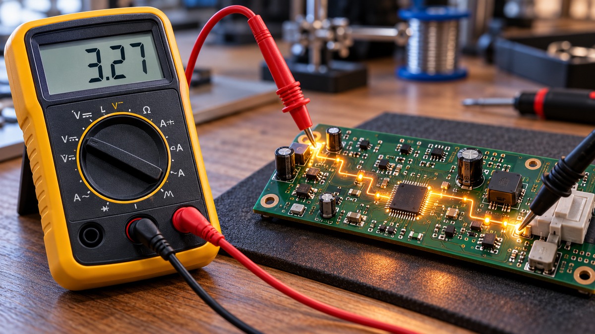
A voltage reading starts with an attenuator. The MIT report describes its voltage module as a precision programmable attenuator with four ranges, built as a four-tap resistor divider. The divider reduces the input by a fixed ratio for the range in use, so the converter sees a voltage it can handle. The same report says the module divides the voltage at the input terminals by a fixed value to produce a scaled voltage for the back end.
The displayed number is therefore the converter’s output scaled back by the division ratio. If the divider cuts the input to a tenth of its value, the meter must multiply the converter’s reading by ten before showing it. Ratios and ranges are design choices made by the manufacturer, and the sources checked do not list ratios for any commercial meter. The principle is what matters here: the converter measures a reduced signal, and the meter rebuilds the full value from a known ratio.
Range selection decides which ratio applies. The Klein manual says the meter “defaults to auto-ranging measurement mode” and that auto-ranging “automatically determines the most appropriate measurement range” for the test being conducted. A range can be forced with the RANGE button. The manual does not explain the internal switching logic, so this article does not describe it.
The Klein catalog page describes the MM420 as having “automatic ranging true root mean square (TRMS) technology for increased accuracy.” The sources checked do not explain how that TRMS calculation is carried out inside the meter. This article reports the listing’s statement and nothing more.
Current: a shunt and a voltage drop
To measure current, the meter places a known low-value resistance in its path. The MIT report calls this a selectable shunt resistance “designed to be connected in series with a load.” A buffer amplifier scales the voltage across that resistance so that it is proportional to the series current. The report uses Ohm’s law, V = IR, so the voltage across the shunt equals the current multiplied by the shunt value. Because the reading comes from a drop across a known resistance, the meter must sit in series with the circuit it measures.
A small shunt drop is hard to read directly, so it is usually amplified first. The Analog Devices wiki describes a current shunt monitor that amplifies “the small differential voltage drop across the shunt” by a fixed gain. Its example chip, the AD8210, uses a gain of 20. That figure belongs to the chip in the example, not to a multimeter. The general point, that a shunt drop needs amplification before a converter can read it, is the part that carries over to meters.
Current inputs have limits that come from the manual. The Klein manual says “Do not attempt to measure more than 10A.” It also lists “500mA / 600V and 10A / 600V” fuses under overload protection. The sources checked do not explain how those fuses relate to the shunt, so this article does not describe that relationship.
Resistance: a known current and a measured voltage
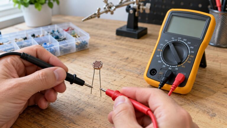
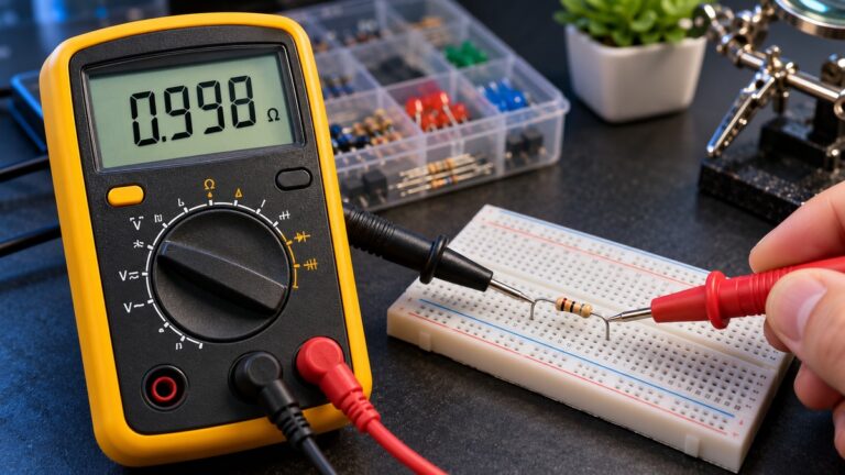
An ohmmeter does not sense resistance as such. It forces a known current through the component and reads the voltage across it. The WPI lab handout gives the principle in its own words: with a known current through a resistor, the voltage measured across the resistor is proportional to its resistance. Ohm’s law then gives the resistance as the measured voltage divided by the known current.
The MIT report describes its resistance module as a precision voltage-controlled current source that applies a constant current to the device under test. An amplifier buffers the voltage developed across the load, and that voltage tracks the resistance. The current is the fixed reference, and the voltage is the measurement.
An older analog design shows the same idea from the other side. NJIT’s lab notes describe a series ohmmeter, with a known resistance in series with an internal source, that is zero-adjusted by short-circuiting its input. The meter’s scale then shows how much the unknown resistance reduces the current. The notes present this as a teaching design, so it is not a description of the digital meter in front of you.
Connection matters because the meter reads whatever it is connected across. The Wayne State handout says the resistor to be measured “must not be connected to any other components.” The same handout notes that when the ohmmeter is connected across a network of resistors, the reading is the equivalent resistance of that network. A single-part reading therefore needs a single part, and a network reading is a different quantity.
Open leads produce an overload indication. The Klein manual says that when the test leads are not connected across a resistor, the display shows “O.L.” and “This is normal.” The same note says a failed resistor under test also shows “O.L.”, so the display alone does not tell you which of the two causes applies.
Reading the display
Once the converter has a value, the meter shows it with a unit and a decimal point. The Klein manual’s resistance table lists range steps such as 400.0, 4.000k and 40.00k, with a resolution figure for each. That table shows that the displayed decimal position changes as the range changes. The display format is a model-specific detail, so the table applies to the MM420 only.
Some functions have their own signal settings. The MM420 manual lists a diode test with a maximum test current of 1.8 mA and an open-circuit voltage of 3.9 V DC. The manual lists a continuity signal that sounds below 50 ohms. These figures are useful for understanding what the meter sends into a component, but they are the MM420’s figures and should not be applied to other models.
Common misunderstandings
- The meter does not read the input voltage directly. The MIT report shows an attenuator that scales the signal before the converter reads it.
- A current reading does not come from a parallel connection. The MIT report describes the current module as designed for series connection through a known shunt.
- An ohms reading is not a property of the meter alone. The resistor’s connections matter, as the Wayne State handout notes.
- An O.L. display does not identify its cause. The Klein manual says open leads and a failed resistor can both show O.L.
- Meters are not identical inside. The MIT report is a student design, and the sources checked do not show that every commercial meter uses the same divider values or converter.
Where to go next
For a look at how a voltage-only tool reads a signal, see the guide to how voltage testers work. For a related task with a meter in voltage mode, see the guide to testing AC voltage with a multimeter.
FAQ
Does a multimeter measure voltage directly?
Not in the sense that the converter reads the terminal voltage at full size. The MIT report describes a voltage module that divides the input by a fixed ratio, and the back end converts the scaled voltage to a number.
Why must the meter be in series for a current reading?
The current module is a shunt designed to be connected in series with a load. The current through the shunt sets the voltage across it, and the meter converts that voltage into the current reading.
How does a meter read ohms without a resistance sensor?
It sends a known current through the resistor and measures the voltage across it. Ohm’s law, V = IR, gives the resistance. The WPI lab handout and the MIT report both describe this method.
Why must the resistor be isolated before an ohms reading?
The Wayne State handout says the resistor must not be connected to any other components. Other parts in the circuit change the equivalent resistance the meter reads.
What does auto-ranging do?
The Klein manual says the meter defaults to auto-ranging and selects the most appropriate range for the measurement. A range can still be forced with the RANGE button.
Do all digital multimeters use the same circuits?
The sources checked describe the three principles, not one circuit for all meters. They do not show that every meter uses the same divider ratios, shunt values or converter.
What we could not verify
The sources checked do not cover the following points.
- The internal circuit of any commercial meter. The MIT report is a student design, and the Klein manual gives no schematic.
- The source for the sentence that work on mains circuits can kill. The site rule asks for three sources per safety claim, and none of the sources checked states that sentence. It is site guidance.
- The basis of a CAT rating, and the CAT rating of any model other than the MM420 in its own manual.
- How true RMS is calculated in the MM420, beyond the listing’s statement that it uses TRMS technology.
- The resolution, sampling and accuracy of any meter other than the MM420 figures in its manual.
- Any Keysight content on DMM front ends. Keysight pages returned 403 to curl, so they are not used.
Sources
- Fluke, What is a Digital Multimeter?: https://www.fluke.com/en/learn/blog/digital-multimeters/what-is-a-digital-multimeter
- Klein Tools, MM420 instruction manual: https://data.kleintools.com/sites/all/product_assets/documents/instructions/klein/MM420%20Instructions_web.pdf
- Klein Tools, Digital Multimeter, Auto-Ranging, 600V (MM420) product page: https://www.kleintools.com/catalog/multimeters/digital-multimeter-auto-ranging-600v-0
- MIT 6.101, All-analog Digital Multimeter project report: https://web.mit.edu/6.101/www/s2018/projects/chinnery_Project_Final_Report.pdf
- WPI, Design and Construction of a Virtual Ohm Meter, lab handout: https://users.wpi.edu/~sullivan/ME3901/Laboratories/01-LabVIEW-Intro_Labs/Lab1-Resistors.htm
- Wayne State University, The DC Power Supply and the Multimeter, lab handout: https://neuron.eng.wayne.edu/auth/ece3310/power_supply_multimeter.pdf
- Analog Devices Wiki, Measuring very small resistances, A Milliohm-meter: https://wiki.analog.com/university/courses/tutorials/alm-milli-ohm-meter
- NJIT ECE 291, Lab 1: Introduction to the laboratory basic electronics instruments: https://ecelabs.njit.edu/ece291/lab1.php