How Does a Multimeter Measure Resistance
As an Amazon Associate we earn from qualifying purchases.
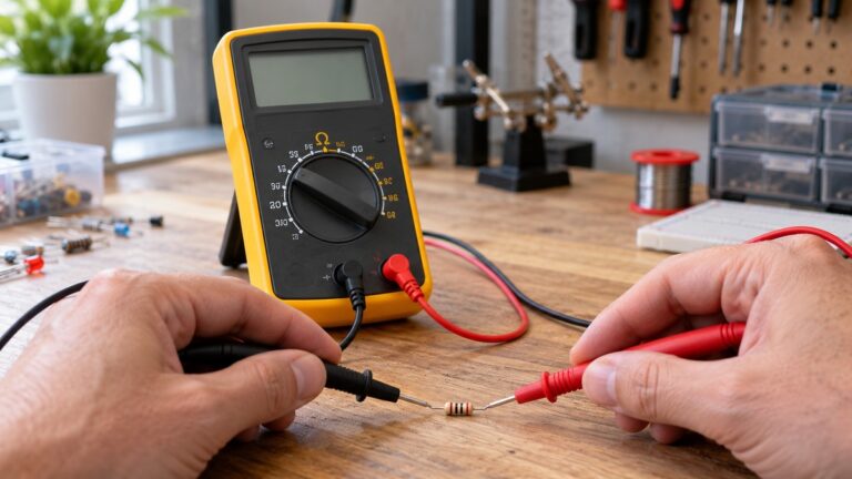
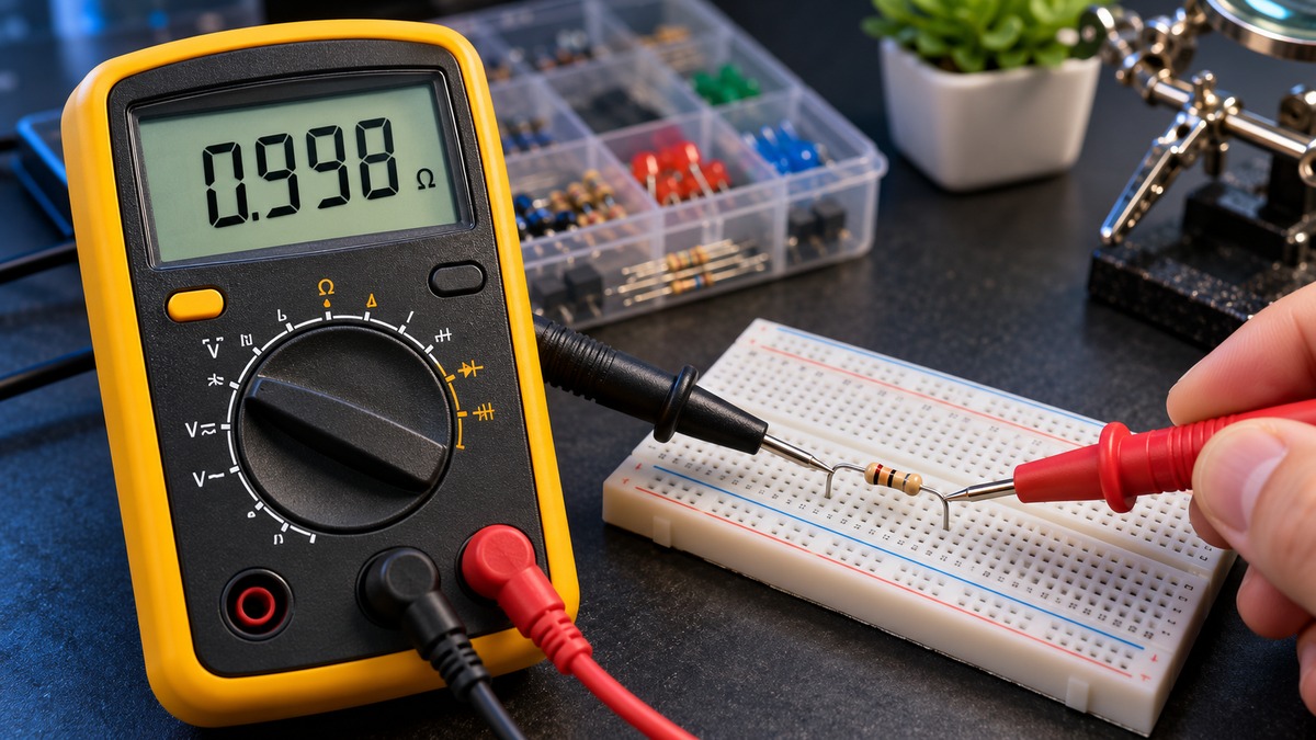
How does a multimeter measure resistance? It sends its own small, known current through the part, reads the voltage that appears across the part, and divides that voltage by the current. The quotient is the resistance, found with Ohm’s law. The same idea explains why the part must be isolated from live power, why other paths across the probes change the reading, and why an open circuit shows OL. This article covers the principle only. It gives no steps for live circuits, and the sources we opened do not state the test current for any specific meter model.
Quick answer
- Resistance mode is for a part on a bench or a circuit that is de-energized. Read the CAT rating from the listing or manual.
- The meter sends a known current through the part, measures the voltage across it, and divides voltage by current (Ohm’s law).
- Power must be off, and parallel paths or lead resistance change the number on the display.
- OL means the reading is beyond the meter’s range or the path is open. A near-zero value can come from the leads.
Electrical safety
Work on mains circuits can kill. Before you measure anything, check that the meter’s CAT rating suits the circuit you are testing, and read the rating from the listing or the manufacturer’s manual. Panel and service work belongs to a licensed electrician.
The principle below is low-voltage bench work: a part on a bench, or a circuit that has been de-energized. The Klein MM320 manual tells the user not to measure resistance or continuity on a live circuit, and the Klein MM400 manual repeats that warning. Its warnings also say that “Failure to observe these warnings can result in severe injury or death.”
The Fluke primer “ABCs of DMMs” lists contact with an AC power source while in resistance mode among the common situations that lead to meter failure. In its current-measurement section, the same primer adds that “Even small amounts of current can be dangerous.” Resistance mode is therefore not a way to probe energized wiring.
The Klein MM320 manual puts the shock concern at voltages above 25 V AC RMS or 25 V DC, and says such voltages pose a shock hazard. It also warns against using the meter on a circuit whose voltage exceeds the meter’s category rating. The Klein MM400 manual states a CAT III 600V rating for that model only. For any other meter, the listing does not state a CAT rating in the sources we opened, so read the rating from that meter’s own listing or manual before use. None of these sources makes a meter suitable for household mains, and nothing in this article does either.
The principle: a known current and Ohm’s law
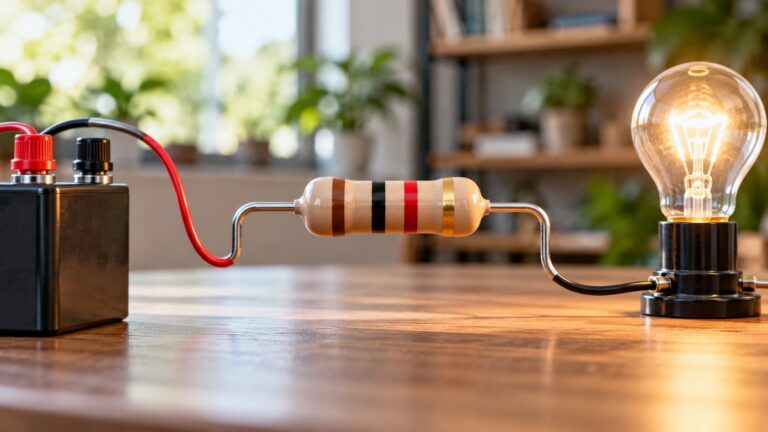
Ohm’s law ties three quantities together. The Fluke primer states that “Ohm’s Law explains the relationship between voltage, current and resistance.” The Southern Methodist University physics handout defines the resistance of a device as the voltage across it divided by the current through it, written R = V/i. A multimeter in resistance mode cannot read a resistor directly. It has to build that ratio from two quantities: one it controls, and one it measures.
The Keysight application note makes the same point from the instrument side. It describes resistance measurement as “merely a combination of sourcing and measuring voltage or current based on Ohm’s law.” The note then says that because most DMMs use an automatic resistance mode, “the test current is essentially fixed for each range.” The fixed current is the known quantity, and the meter converts the measured voltage into ohms.
Our own assumption, for illustration only: suppose the test current on one range were 1 mA, and the meter measured 2.2 V across a part. Then R = 2.2 V divided by 0.001 A, which equals 2,200 ohms. The sources we opened do not give 1 mA for any specific meter. The number exists only to show the arithmetic.
Ranges follow from the same arithmetic. With a fixed test current, a larger resistance produces a larger voltage across the part, so the meter has to pick a band of values that fits the reading. This follows from V = IR and is our own reasoning. The Fluke primer gives the overall span: most DMMs measure down to 0.1 ohm, and some measure as high as 300 megohms.
Auto-ranging and manual-ranging differ only in who picks the band. The Klein MM400 is described as an auto-ranging multimeter, while the Klein MM320 is a manual-ranging multimeter. For a wider comparison of auto-ranging meters, see our auto-ranging digital multimeter roundup.
Why the part must be isolated from power
The Fluke primer says resistance measurements “must be made with the circuit power off”, because otherwise the meter or the circuit could be damaged. The reason follows from the principle. The reading assumes that the only current through the part is the test current the meter supplies. If a supply is driving its own current through the part, the voltage the meter reads is no longer the voltage produced by its test current, so the ohm figure does not describe the part. The sources we opened do not spell out that mechanism. The explanation here is our own reasoning.
Some meters protect the ohms function against accidental contact with voltage. The Fluke primer warns that “The level of protection may vary greatly among different DMM models.” Protection of that kind is therefore not a reason to measure on a live circuit.
Diodes and semiconductor junctions complicate the picture. The Fluke primer says that a test voltage below 0.6 V dc keeps junctions from conducting, so a resistor isolated by a diode or junction can be measured, and that this “often allows you to test resistors on a circuit board without unsoldering them.” That passage explains why the test voltage is kept low. It does not permit measuring with power on.
Why parallel paths change the reading
A resistance reading describes whatever sits between the two probe tips. Any other conducting path between those tips sits in parallel with the part, and parallel paths lower the combined resistance. This is our own reasoning from the parallel-resistance rule. As an illustration, suppose a 1,000 ohm part has another 1,000 ohm path across the same tips. The combined value is 1 divided by (1/1000 + 1/1000), which is 500 ohms. The sources do not present this example.
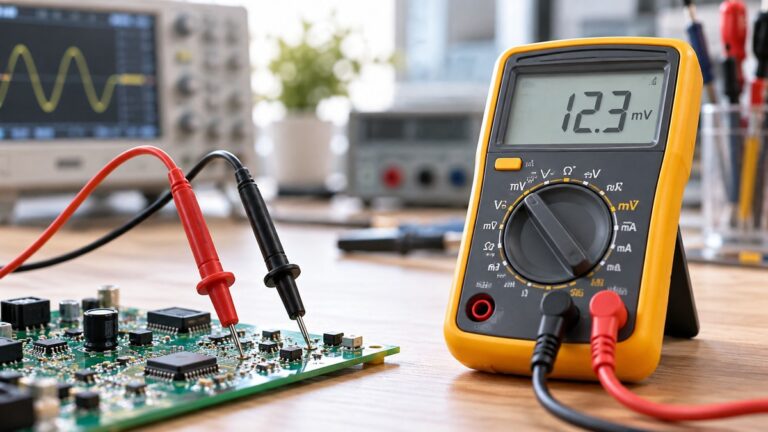
Keysight’s note lists leakage current among the major error factors in resistance measurement, alongside lead resistance and thermal EMF. The note names the factor but does not give a size for the error, so this article does not give one either. A leakage path across the part is, in effect, one more parallel path.
Lead placement matters for the same reason. The Southern Methodist University handout describes the voltmeter-ammeter method, in which the voltmeter reads “the voltage across both A and R” in one of its two arrangements. In that arrangement the calculated resistance comes out too large, and the error becomes small when the unknown resistance is large compared with the ammeter’s internal resistance. A handheld meter does not use two instruments, but the reading still depends on what the leads are actually across.
Lead resistance and low readings
The test leads add resistance of their own. The Fluke primer gives a typical test lead resistance of about 0.2 to 0.5 ohm, and says that if the resistance in the test leads is greater than 1 ohm, the leads should be replaced. For a part with a very low resistance, that lead figure is a large share of the total.
The Fluke primer states that for accurate low-resistance readings, the lead resistance must be subtracted from the total. Keysight goes further. It says it is “essential to use a 4-wire connection configuration in low resistance measurements” because the residual lead resistance is comparable to the resistance of the device under test. In a four-wire arrangement, “one pair of leads to source the current and the other pair of leads to measure voltage,” which keeps the current leads out of the voltage reading.
The Fluke calibration article describes how a four-wire setup “allows you to compensate for lead resistance errors in a resistance measurement.” It also notes that many handheld meters do not support that connection.
A reading close to zero therefore means the meter sees a very low resistance between its probe tips. When the part is below the lead figure, the reading mostly reflects the leads. The sources we opened do not give a pass value for any part, so a near-zero reading cannot be called good or bad on this evidence alone.
Why readings show OL
The Fluke primer says that “Infinite resistance (open circuit) is read as “OL” on the Fluke meter display, and means the resistance is greater than the meter can measure.” In principle terms, an open path gives no complete route for the test current, so the meter cannot form a valid ratio within the range it is set to, and it reports overload. This is our own reasoning.
Klein’s MM320 manual describes the OL indication for open test leads and for a failed resistor under test, and calls it normal. The Klein MM400 manual lists OL as the overload indication for that meter. Read together, these sources treat OL as a display of over-range or open-path conditions, not as a value.
OL is not a zero reading, and it is not a fault report on its own. The Klein statement applies to the open-lead and failed-resistor cases the manual describes, not to every OL reading on every meter. For a related but separate test, see our continuity checker guide.
Common misreadings
- OL does not mean zero ohms. It means the reading is beyond the meter’s range or the path is open.
- A low reading does not prove that a part is good. Lead resistance and any parallel path add to what the meter displays.
- Protection in the ohms function is not permission to measure a live circuit. The Fluke primer says the protection level varies by model.
- A resistance function does not set the voltage category. The CAT rating comes from the listing or manual, and the sources here give one only for the Klein MM400.
How we chose
Each source had to be a manufacturer document from Fluke, Keysight or Klein, or a university physics page, opened with curl on 2026-10-22. Quoted text had to appear in the fetched content before it was used. Search results were used only to find candidate URLs, and no search snippet is cited. Pages that returned 403 or could not be reached were dropped.
The candidate list had ten URLs. Seven returned content, and six of those are cited. One Fluke how-to page was opened, and no passage from it is used. Two Keysight pages returned 403, and one Lehman lab PDF could not be reached. The Keysight link opened an asset page with the note’s text rather than the PDF file, and the Fluke primer is hosted on a retailer domain while naming Fluke Corporation as its publisher. Both points are recorded in the sources file.
The article is limited to the principle of resistance measurement. Procedures were left out on purpose, and so were any steps for live wiring. The example values are labelled as our own assumptions. The internal links point only to posts that returned HTTP 200 when checked.
What we could not verify
The sources we opened do not state the test current for any named meter. Keysight says the current is essentially fixed for each range on most DMMs, but it gives no value for a model. The 1 mA figure in this article is an illustration only.
The sources do not give the size of the error from leakage current or from a parallel path, and they do not say how much ohms-mode protection a given meter provides. The Fluke primer says the protection level varies greatly among models, and gives no figure.
A CAT rating appears only for the Klein MM400 in the sources we opened. The listing does not state a CAT rating for any other meter covered by this article, and none of the sources gives a general rating for meters in this category.
The sources do not give a pass or fail value for any part, so readings from a real circuit cannot be judged against any figure in this article.
Frequently asked questions
Does the meter supply its own current in resistance mode?
Yes. Keysight describes the task as sourcing and measuring a quantity under Ohm’s law, and says the test current on most DMMs is fixed within each range. The sources we opened do not give that current for a named model.
Why does the circuit need to be off?
The reading assumes the meter’s own current is the only current through the part. The Fluke primer says the meter or circuit could be damaged otherwise, and the Klein manuals repeat the rule as a warning. The mechanism described here is our own reasoning.
What does an OL display indicate?
OL indicates that the resistance is above what the meter can read, which usually means the path is open. Klein’s MM320 manual says the display shows OL with open test leads or a failed resistor under test, and calls that normal.
Why can a part that looks like a short read a fraction of an ohm?
The test leads have their own resistance, which the Fluke primer places at about 0.2 to 0.5 ohm. A part whose resistance is below that figure mostly shows the leads. Keysight treats a four-wire arrangement as essential for low-resistance work.
Can a resistor on a board be measured without desoldering it?
The Fluke primer says a test voltage under 0.6 V dc can avoid conduction through diodes and junctions, and that this often lets a resistor be checked without unsoldering it. The power-off rule still applies, and the sources do not describe how much other paths on a given board distort the reading.
Does a resistance function make a meter safe for household mains?
No. The sources do not support that claim. The Klein MM400 states CAT III 600V for its own model, and the Klein MM320 warns against use on circuits above its category rating. Household mains work belongs to a licensed electrician, as the safety section says.
Sources
- Fluke Calibration, “4 Most Accurate Resistance Measurement Methods” (opened 2026-10-22): https://www.fluke.com/en/learn/blog/calibration/resistance-measurement-methods
- Fluke Corporation, “ABCs of DMMs” application note, PDF on a retailer domain (opened 2026-10-22): https://www.newark.com/pdfs/techarticles/fluke/ABCs_of_DMMs.pdf
- Keysight Technologies, “Wide Range of Resistance Measurement Solutions from µΩ to PΩ” asset page (opened 2026-10-22): https://www.keysight.com/us/en/assets/7018-05031/application-notes/5992-1212.pdf
- Klein Tools, MM320 instruction manual (opened 2026-10-22): https://data.kleintools.com/sites/all/product_assets/documents/instructions/klein/MM320-1390422ART%20-%20WEB.pdf
- Klein Tools, MM400 instruction manual (opened 2026-10-22): https://data.kleintools.com/sites/all/product_assets/documents/instructions/klein/MM400_1390110ART_WEB.pdf
- Southern Methodist University, Physics, Ohm’s Law laboratory handout (opened 2026-10-22): https://physics.smu.edu/scalise/emmanual/ohm/lab.html