How to Test a Photoresistor With a Multimeter
As an Amazon Associate we earn from qualifying purchases.
How to test a photoresistor with a multimeter comes down to two resistance readings, one in dim light and one in bright light, taken with the part out of its circuit and the power off. A photoresistor, also called a light dependent resistor (LDR), has a resistance that falls as more light reaches it. The method below uses only the meter’s ohms function and applies no voltage to the part. One manufacturer datasheet gives reference figures at a stated light level. The remaining steps come from a meter maker’s guide and from two university lab manuals.
Quick answer
- Test the part out of its circuit, with the power off and no voltage applied.
- Use the meter’s ohms setting to read the part in room light, in the dark, and in bright light.
- Compare the dark reading with the datasheet for the same part number, and treat the other readings as comparisons.
- Read the CAT rating from the listing or the manual before any measurement.
Electrical safety first
Work on mains circuits can kill. This guide covers only a low-voltage bench check of a part that has been removed from its circuit. It gives no steps for live mains, panels, outlets or service wiring, and nothing in it applies to a circuit connected to mains.
Before you measure anything, check that the meter’s CAT rating suits the circuit you are testing, and read the rating from the listing or the manufacturer’s manual. If the listing does not state a CAT rating, do not assume one, and do not use that meter on any circuit that needs a rating. The ECAO/IBEW trade safety advisory says to use only multimeters that display both a CSA mark, or an equivalent, and a CAT designation. Fluke advises choosing a meter rated for the highest category you could use it in, with a voltage rating that matches or exceeds that situation. For what one of those ratings means in practice, see our explainer on the 600V CAT III rating.
Making contact with a live circuit can result in serious injury or death, according to the same advisory. MIT’s environmental health and safety page says that even contact with standard 110-volt circuits can be lethal under certain conditions, and it states that current, not voltage, is the killing factor in electrical shock. Fluke’s article on electrical safety myths adds that test leads which are poorly made, worn, or not rated for the job can pose a serious shock hazard.
Panel and service work belongs to a licensed electrician. MIT’s page says that only licensed electricians are permitted to work on building infrastructural electrical systems. Northwestern’s electrical safety program says to ensure that only qualified electricians maintain, repair, or install electrical equipment, systems, and installations. Fluke’s myths article says that where the power cannot be shut down, only qualified electricians and technicians should work on energized systems.
What you need
- A digital multimeter with an ohms (Ω) setting. On many meters that setting shares a spot on the dial with continuity, capacitance and diode modes, so read the dial labels before you start.
- Test leads rated at the same or greater voltage than the meter, as the trade advisory recommends.
- The photoresistor’s datasheet, with its part number. Luna’s datasheet tells the reader to contact the manufacturer for recommendations on specific test conditions and procedures.
- A light source you can hold at a set distance. The Fiore lab manual uses a pen light placed about 25 centimeters from the part.
- A dark cover, such as a piece of black cloth, or your hand.
- A ruler or tape measure, so the distance from the light is recorded and not estimated.
For a wider look at meter types, see our roundup of auto-ranging digital multimeters. For a different check, such as continuity, see how to use a continuity tester.
Reference figures from the datasheet
The datasheet we opened covers the PDV-P8104, a cadmium sulfide (CdS) photoconductive cell. The copy we opened is hosted on an MIT server, and its header names Luna Optoelectronics. The table lists its figures with the conditions printed beside them.
| Item | Figure in the datasheet | Condition printed in the datasheet |
|---|---|---|
| Illuminated resistance | 27 kΩ minimum, 60 kΩ maximum | 10 lux at 2856 K |
| Dark resistance | 2 MΩ minimum | Timed: “After 10 sec.” at 10 lux |
| Rise time | 60 ms | 10 lux at 2856 K |
| Fall time | 25 ms | After 10 lux at 2856 K |
| Spectral range | 400 to 700 nm, typical 520 nm | Listed under “Flooded” |
| Applied voltage maximum | 150 V | Absolute maximum ratings |
| Operating and storage temperature | -30 to +75 °C | Absolute maximum ratings |
The resistance figures use one light level, 10 lux. A footnote defines a value at 100 lux, but the table gives no number for that level, so the datasheet has no bright-light figure to compare against. The 150 V applied-voltage maximum is a rating to know. A bench ohms check applies no voltage to the part, so the limit does not set any step.
Steps for the bench check
Each step names the source it follows. Work through them in order.
- Turn the power off and take the part out of its circuit. Fluke’s resistance guide lists turning off power to the circuit as its first step. The same guide says a capacitor in the circuit must be discharged before any resistance reading, and that results are best when the component is removed, because other components in parallel can affect the reading.
- Set the meter to ohms. Turn the dial to the resistance position. Insert the black lead into the COM jack and the red lead into the VΩ jack, as Fluke’s guide describes.
- Check the open-lead display. With the leads not touching anything, Fluke says the display should show OL. An MΩ symbol can appear, because open test leads have very high resistance.
- Choose a range. Fluke says a digital meter in autorange mode picks the best range once the leads are connected to a component, and that the range button sets a range by hand. The Annamalai University manual says to adjust the meter to a suitable resistance range. Because the datasheet’s dark minimum is 2 MΩ, the range you use must be able to show at least 2 MΩ (our own assumption, based on that minimum).
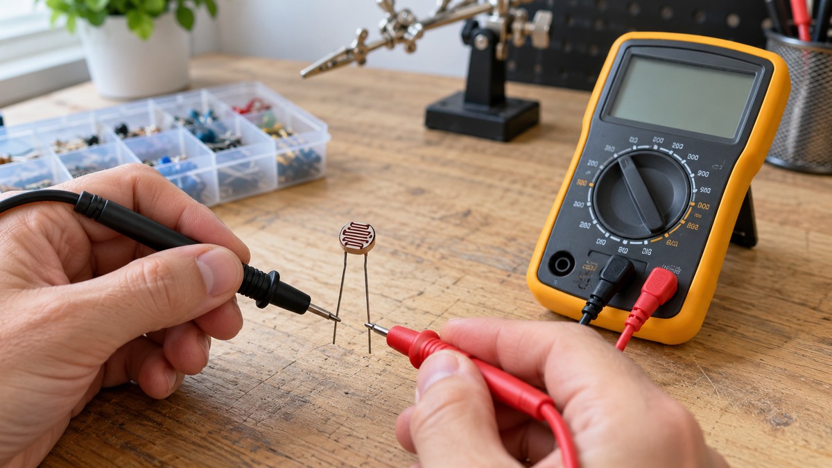
- Connect the leads across the part. Fluke’s guide says to connect the test leads across the component being tested. Keep the leads on the two terminals of the part.
- Record the room-light reading. The Fiore manual says to measure away from any windows and not to block the ambient room light. Record this reading as the normal value.
- Record the dark reading. Place a finger or a piece of black cloth over the part. The Fiore manual says to block all light and to make sure the leads are not also touched. The Annamalai manual covers the part with a black cloth in the same way. Record the reading and compare it with the 2 MΩ minimum. Note the time when you start reading, because the datasheet ties its dark figure to a timed condition.
- Record the bright reading. Shine the pen light directly onto the part from about 25 centimeters, as the Fiore manual does, and record the reading. The datasheet gives no bright-light number for this part, so compare this reading only with your other readings.
- Read at several distances. Move the light closer to the part and farther from it. Record a reading at each distance, then plot resistance against distance. The Annamalai manual does this with a lamp and plots resistance against 1/r², where r is the distance from the lamp, as a measure of light intensity.
Reading the results
The trend matters more than any single value. The Annamalai manual says that the more light strikes a CdS cell, the lower its resistance. The same manual says a simple CdS cell can span a very wide range of resistance, from a low value in bright light to a very high value in darkness, and it adds that these figures are not accurate. Use the trend to judge whether the part responds to light at all, and use the datasheet only for the part it describes.
A dark reading below the 2 MΩ minimum does not match this datasheet. The sources we opened do not say why that happens, so write down the part number, the light condition and the timing before you draw a conclusion. A room-light reading can be compared with the 27 kΩ to 60 kΩ range only if you know that the light level is 10 lux. The sources we opened do not show how to set 10 lux at home.
The datasheet’s spectral range runs from 400 to 700 nm, with a typical value of 520 nm. The Annamalai manual notes that many commercially available CdS cells peak between 500 nm and 600 nm, which is green light. Our own reading of these two sources is that a light source of a different color may give a different response. The sources we opened do not cover that for this part.
Common mistakes
- Measuring with the power on. Fluke’s guide says to turn the power off first, the ECAO/IBEW advisory says to de-energize equipment first when that is practicable, and the SUNY Canton lab procedures say to confirm circuit resistance before connection to the power supply.
- Leaving the part in its circuit. Fluke says other components in parallel can affect the reading, so a reading taken in the circuit may not describe the part alone.
- Plugging a lead into the wrong jack. The ECAO/IBEW advisory says to make sure test leads are in the correct input jacks.
- Touching the leads while blocking the light. The Fiore procedure asks for the leads to stay untouched while the part is covered.
- Using one part’s figures for another part. The table above belongs to the PDV-P8104. Other photoresistors can differ, so use the datasheet that matches your part number.
- Treating a distance as a lux value. The Fiore procedure places a pen light at about 25 centimeters but gives no lux figure, so the bright reading is a comparison, not a measured light level.
How we chose
The brief for this draft asked for light-level figures from a manufacturer datasheet only, so the draft uses one datasheet for its numbers. The bench method comes from a meter maker’s resistance guide and from two university lab manuals that describe the same dark and bright readings. The safety statements come from a meter maker, a safety advisory, and two university pages, and each one names the source it rests on. We opened each page on 2026-10-21 and checked every quotation against the text we saved. Pages that returned a 403 error, or that loaded no article text, were left out. Search results helped us find candidate pages, and none of them is cited.
What we could not verify
The sources we opened do not cover the following points, so this draft does not make claims about them.
- The only datasheet we read is for the PDV-P8104, in a revision dated 10-24-16. The copy is hosted on an MIT server, and the sources we opened include no page from the manufacturer for it.
- The datasheet gives no bright-light figure for this part. Its footnote defines a 100 lux value, but the table gives no number for it.
- No source we opened says how to set a light level of 10 lux or any other level at home, or which light meter to use for it.
- No source gives a wait time before a dark reading, beyond the datasheet’s timed dark condition.
- No source we opened gives the test current or test voltage the meter applies in ohms mode, so this draft does not describe either.
- This article names no meter. If the listing for your meter does not state a CAT rating, the listing does not state a CAT rating, and that meter is not one to use on a circuit that needs one.
- The Fiore and Annamalai documents are teaching manuals, not manufacturer manuals. The procedures they describe are general methods and do not cover one part’s behavior.
- The sources cover cadmium sulfide cells. They do not cover other light-sensitive parts.
Frequently asked questions
Can I test a photoresistor while it is still in a circuit?
Fluke says the best results come when the component is removed from the circuit, because other components in parallel can affect the reading. Turn the power off in either case.
What resistance should a photoresistor show in the dark?
For the PDV-P8104, the datasheet gives a dark resistance of 2 MΩ minimum, under the timed condition printed beside it. Other parts have their own figures, so use the datasheet that matches your part number.
What does it read at 10 lux?
The same datasheet gives 27 kΩ minimum and 60 kΩ maximum at 10 lux with a 2856 K light source. A bench reading is comparable to that range only if you can reproduce the 10 lux level, and the sources do not show how to do that at home.
Do I need a light meter?
A light meter would give a lux number, but the sources we opened do not cover any particular meter. The Fiore manual uses a pen light at about 25 centimeters and gives no lux value, so the readings in this method are comparisons.
Why does the power-off step matter for this test?
Fluke lists turning power off as the first step of a resistance reading. The SUNY Canton lab procedures say to confirm circuit resistance with an ohm meter before connection to the power supply. The ECAO/IBEW advisory says equipment must be de-energized first when that is practicable.
Is any voltage applied to the part during this check?
No. The method asks you to remove the part from its circuit and take the ohms reading without connecting any supply. The datasheet’s 150 V applied-voltage maximum is therefore not a step in this check, and a part that has been powered should be checked only after the power is removed.
Bottom line
Test the part with the power off and out of its circuit, and compare your dark reading only with a datasheet for the same part number.
Sources
- Fluke, How to Measure Resistance with a Digital Multimeter: https://www.fluke.com/en-us/learn/blog/digital-multimeters/how-to-measure-resistance
- Fluke, Guide to digital multimeter safety: https://www.fluke.com/en-us/learn/blog/safety/multimeter-guide
- Fluke, Four Myths About Electrical Safety That May Surprise You: https://www.fluke.com/en/learn/blog/safety/electrical-safety-myths
- ECAO/IBEW Trade Safety Advisory on multimeters (reprinted in part with permission of Fluke Electronics Canada): https://www.ihsa.ca/pdfs/safety_bulletins/safety_bulletin_multimeters.pdf
- MIT Environmental Health and Safety, Electrical Safety: https://ehs.mit.edu/electrical-safety
- Northwestern University, Electrical Safety Program: https://www.northwestern.edu/environmental-health-safety/docs/safety-programs/electrical-safety-program.pdf
- Luna Optoelectronics, PDV-P8104 CdS Photoconductive Photocells datasheet (copy hosted by MIT): https://eepmagicb.mit.edu/document/Photoresistor.pdf
- James M. Fiore, Semiconductor Devices lab manual, section 2.4 Procedure (LibreTexts): https://eng.libretexts.org/Bookshelves/Electrical_Engineering/Electronics/Laboratory_Manual_-_Semiconductor_Devices_-_Theory_and_Application_(Fiore)/02%3A_Resistive_Sensors/2.4%3A_Procedure
- Annamalai University, B.E. Electronics Lab Manual, LDR experiment: https://annamalaiuniversity.ac.in/studport/download/engg/E%26I/labmanuals/B.E-IV%20semester-Electronics%20lab.pdf
- SUNY Canton College, ELEC141 Industrial Controls Safety: Operating Procedures: https://www.canton.edu/media/employee/elec141/safety-operation.pdf