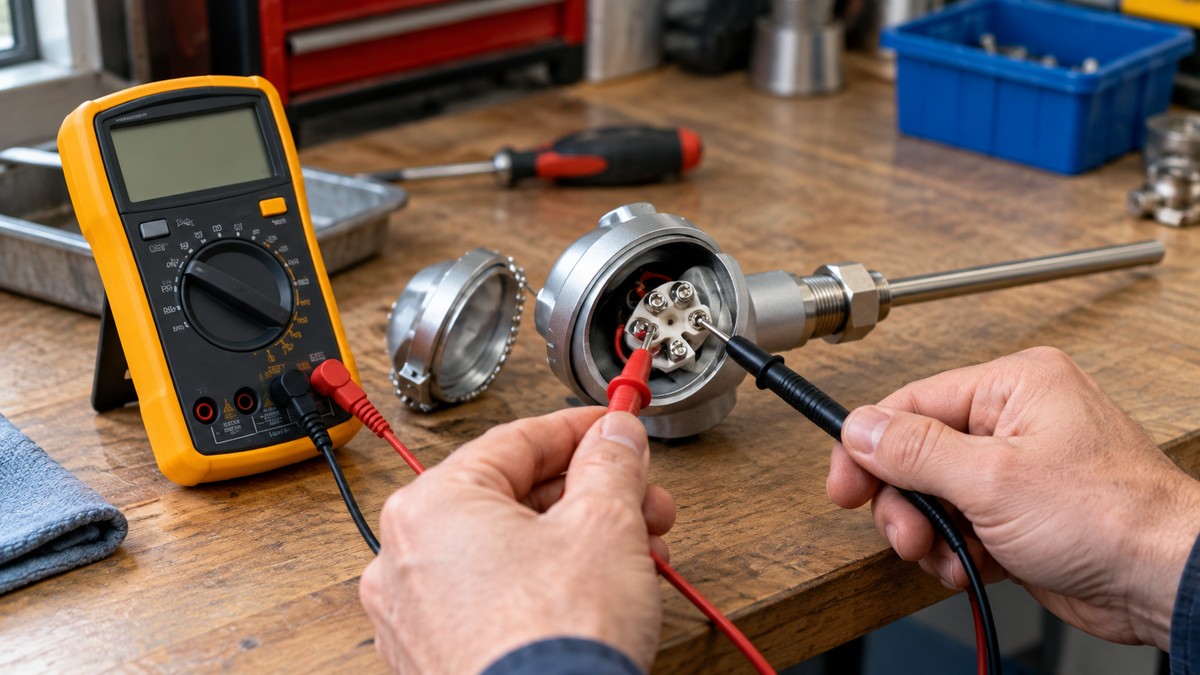
How to Test an RTD With a Multimeter
As an Amazon Associate we earn from qualifying purchases.
How to test an RTD with a multimeter means one bench check: disconnect the sensor, measure its resistance at a known temperature, and compare the reading with the expected value for that temperature. Fluke’s calibration guide describes this method, and its Pt100 calculator gives values from the IEC 60751:2008 equation. This guide covers only that low-voltage check. It does not cover a sensor that is still wired into a running loop.
Electrical safety
Work on mains circuits can kill. Before you measure anything, check that the meter’s CAT rating suits the circuit you are testing, and read the rating from the listing or the manufacturer’s manual. Panel and service work belongs to a licensed electrician.
Fluke’s safety course says a mistake while working on a high-energy electrical system can be deadly. Fluke’s guide to multimeter safety adds that shock occurs when the human body becomes part of an electrical circuit. The Consumer Product Safety Commission’s electrical safety leaflet says home electrical systems are involved in fires and deaths each year. The same leaflet advises a licensed electrician to check a home’s electrical system when it has gone more than 10 years without an inspection, or when warning signs appear.
Keep the controller or transmitter de-energized while you work on the sensor. Fluke’s guide says to assume every electrical component in a circuit is energized until you have taken steps to discharge it. The sources we opened do not give a separate power-down step for RTD checks, so the power-off rule rests on that general advice.
Fluke ties its PPE advice to energized, exposed circuits greater than 50 V. This bench check should not involve such a circuit, because the sensor is disconnected and the loop is de-energized.
How CAT ratings apply
The category rating matters because circuits can carry spikes such as transient overvoltage. Fluke’s guide says to choose a tool rated for the highest category you could potentially use it in, with a voltage rating to match or exceed that situation. Fluke’s partial list of IEC categories is below.
| Category | Fluke’s description from the IEC list |
|---|---|
| CAT I | Protected electronic equipment |
| CAT II | Single-phase receptacle-connected loads such as appliances and portable tools |
| CAT III | 3-phase distribution including single-phase commercial lighting and equipment in fixed locations such as switchgear and polyphase motors |
| CAT IV | 3-phase at the utility connection, outdoor conductors, electricity meters, and service entrances |
Fluke’s list also notes that CAT ratings on test equipment have no relation to the PPE hazard risk categories in NFPA 70E. Fluke says the NFPA 70E edition it cites references the ANSI IEC 61010-1 standard, which defines test tool category ratings. Fluke’s guide also points to independent verification symbols on a meter, which show that an independent lab has tested it. For the meter you own, the listing or manual has to state its CAT rating. The sources we opened give no rating for any model, so this guide does not name one.
Quick answer
- Keep the controller or transmitter de-energized, and disconnect the RTD from its electronics before you connect the meter.
- Place the sensor at a known temperature, using a dry-block or bath with a temperature standard.
- A nominal Pt100 reads 100.0000 Ω at 0 °C, according to the Fluke calculator.
- On a 2-wire sensor the lead wires add to the reading, so count the wires before you start.
What you need
- A digital multimeter with a resistance setting. Fluke’s RTD calibration article says to connect the sensor to a precision instrument capable of measuring resistance, and the sources we opened do not state a resolution. For a meter choice, see our resistance meter roundup.
- A temperature source such as a dry-block or Micro-Bath, plus a temperature standard for comparison.
- The sensor’s datasheet or manual, for its wire count and nominal resistance. Reotemp’s brief uses a “100 ohm .00385 alpha platinum resistor element” as its example, and calls it the de facto standard.
Step-by-step bench check
Step 1: Inspect the meter and leads
Fluke’s guide says to visually inspect the multimeter, probes and accessories for physical damage before you take a measurement. It also says you should never use a damaged meter or damaged test probes. Fluke’s guide says to confirm that a meter works before you rely on it, using a known voltage source or a proving unit. Those checks are for voltage, and the sources we opened give no known-resistance check, so this guide does not describe one.
Fluke’s guide also advises avoiding measurements in humid or damp environments where possible, and checking for flammable dust or vapor nearby.
Step 2: Disconnect the sensor from its electronics
Fluke’s calibration guide says to disconnect the RTD from the electronics when you check it separately from the control system’s temperature indicator. The same guide starts with a related instruction: “Isolate the sensor from the process.” If you are new to checking wiring for open or broken connections, see our guide to using a continuity tester.
Step 3: Identify the wire count
Reotemp’s brief describes 2-wire, 3-wire and 4-wire RTDs. On a 2-wire sensor, the brief says the lead wires and the platinum element become one sensing entity. Its example adds a 6″ length of 24awg stranded copper hookup wire to each side of a 100 ohm element, and the leads then affect the reading.
For 3-wire and 4-wire sensors, the brief explains how the instrument cancels lead resistance. A 3-wire device measures across pairs of wires and subtracts one result from the other, and Reotemp says its design makes sure the leads are all the same length and gauge. A 4-wire device uses a bridge circuit, and the brief says that handles uneven lead lengths and mixed gauges.
The brief says the challenge is to only “see” the resistance of the sensor and to “ignore” the resistance of the leadwires.
These descriptions cover what the instrument does, not a multimeter method. The sources we opened do not give a multimeter method for subtracting lead resistance, so this guide does not describe one.
Step 4: Hold the sensor at a known temperature
Fluke’s article describes a precision source as “a dry-well or bath capable of covering the required temperature range.” Fluke says field checks of temperature sensors can be performed with a dry-block or Micro-Bath, and that a full calibration is best done at the bench. For best accuracy, the guide says to fully immerse a temperature standard in the same dry-well or bath for comparison. Adjust the temperature to each test point before you take a reading.
Step 5: Connect the meter and read the resistance
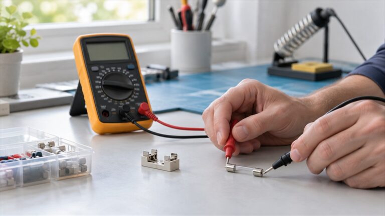
Fluke’s guide says to connect the RTD to a precision instrument capable of measuring resistance. Set the meter to its resistance function and connect it to the sensor leads. On a 2-wire sensor, the reading includes the leads, as Step 3 explains.
Step 6: Record the readings at each test point
Fluke says to record the readings of the temperature standard and of the RTD at each test point. Keep the readings paired, so each RTD value sits next to the temperature standard reading taken with it.
Step 7: Compare with the expected value
Fluke says that when you measure the RTD apart from its measurement electronics, you should “compare the measured resistances to the expected resistance from the applicable temperature table.” The values below show how to set that expected figure.
Reading the results
Fluke’s calculator uses the IEC 60751:2008 equation, R = R0 [1 + A t + B t² + C (t − 100) t³]. The page says its equation and coefficients come from IEC 60751:2008, ASTM E1137-08(2020) and JIS C 1604:1997. For its PT-385 curve, the page lists R0 = 100.0000 Ω, A = 3.9083E-3 and B = −5.775E-7 for 0 °C to 650 °C, with C = 0 in that range. The calculator generates its table on the page, and that table was not in the text we opened. The figures below are our own arithmetic from the equation and coefficients, except the 0 °C value, which Fluke states.
| Temperature (°C) | Expected resistance, PT-385 (Ω) | Basis |
|---|---|---|
| 0 | 100.00 | Nominal R0 stated by Fluke |
| 20 | 107.79 | Our arithmetic from the equation and coefficients |
| 100 | 138.51 | Our arithmetic from the same equation |
The table applies to a sensor with R0 = 100 Ω on the PT-385 curve. Fluke notes that a custom R0 gives calculated values that “will be unique for the thermometer and will not be of standard table value.” Use the sensor’s own R0 when you have it.
The sources we opened do not say what size of difference from the table is normal or abnormal. They also do not describe an open-circuit or short-circuit reading for an RTD, so this guide does not label any reading as a fault. A reading that differs from the table tells you to check the setup, the leads and the temperature reference before you decide anything about the sensor.
Common mistakes
- Measuring while the sensor is still wired to the electronics. Fluke’s calibration guide says to disconnect the RTD from the electronics for a separate check.
- Ignoring the lead wires. Reotemp’s brief says that on a 2-wire sensor the leads become part of the sensing circuit.
- Mismatched leads on a 3-wire sensor. Reotemp says its 3-wire design depends on leads that are all the same length and gauge.
- Using the wrong curve. Fluke’s calculator lists PT-385 and PT-392, which have different coefficients. At 100 °C, our arithmetic gives 138.51 Ω for PT-385 and 139.24 Ω for PT-392, a difference of about 0.73 Ω.
- Skipping the temperature standard. Fluke says a temperature standard immersed for comparison gives the best accuracy.
- Treating a powered loop as safe. Fluke’s guide says to assume every component is energized until it has been discharged.
- Using a damaged meter or probes. Fluke’s guide says never to use a damaged meter or damaged test probes.
For a different sensor type that needs its own check, see our guide to testing a thermocouple with a multimeter.
How we chose
This guide follows only the bench method that the sources we opened describe: the sensor is disconnected from its electronics, measured at a known temperature, and compared with a table or equation. Fluke’s article notes that RTDs are typically checked while the connected device is calibrated, and that a sensor can be calibrated separately when a problem is suspected. This guide covers that separate check. A page counted as a source only when our curl request returned it and the quoted sentence appeared in the fetched text. Pages that returned 403 or a verification challenge did not count. We preferred manufacturer and government pages. Seven pages passed those tests on 2026-10-21. Five of them come from one manufacturer, Fluke, so the set is narrower than the number suggests.
What we could not verify
The sources we opened do not give a tolerance band for any RTD class, so this guide does not say what counts as a failed sensor. They do not describe open-circuit or short-circuit readings for an RTD. The sources we opened do not state a meter resolution, excitation current or self-heating limit. The Fluke calculator’s table was not in the text we fetched, so every table value except the stated 0 °C value is our arithmetic. The sources do not give a multimeter method for lead subtraction on a 3-wire sensor, and they give no CAT rating for any meter.
Frequently asked questions
What should a Pt100 read at 0 °C?
The Fluke calculator gives a nominal R0 of 100.0000 Ω at 0 °C for its PT-385 curve.
Can I test the RTD while it is still wired in?
Fluke’s calibration guide describes a check with the RTD disconnected from the electronics. The sources we opened do not describe an in-circuit resistance check, so this guide does not give one.
Do I need a dry-block or a bath?
Fluke says field checks can be performed with a dry-block or Micro-Bath, and that a full calibration is best done at the bench. The sources we opened do not cover an ice bath as a reference, so this guide does not describe one.
What does a 2-wire reading include?
Reotemp’s brief says a 2-wire setup makes the lead wires part of the sensing circuit, so the reading includes lead resistance. The brief gives no lead resistance figure to use.
What is the difference between PT-385 and PT-392?
Fluke says PT-392 has higher purity platinum wire and is specified with a higher level of accuracy. Its coefficients differ from PT-385, so its table values differ too.
Is a 3-wire or 4-wire sensor more accurate?
Reotemp calls 3-wire the industry workhorse and says 4-wire gives better accuracy, especially with long wire runs. The sources we opened do not give an accuracy figure for either type, so this guide does not compare them numerically.
Is it safe to test an RTD on a running loop?
This guide does not cover a running loop. Fluke’s guide says to assume every electrical component in a circuit is energized until you have discharged it, so do not work on a loop that is still powered.
Bottom line
Disconnect the sensor, measure its resistance at a known temperature, and compare the reading with the value for that temperature on the curve your sensor uses.
Sources
- Fluke, Calibrating and Testing RTD Sensors: https://www.fluke.com/en-us/learn/blog/calibration/calibrating-and-testing-rtd-sensors (opened 2026-10-21)
- Fluke, PT100 Resistance Chart and Calculator: https://www.fluke.com/en-us/learn/tools-calculators/pt100-table-generator (opened 2026-10-21)
- Reotemp, Choosing Between 3-Wire and 4-Wire RTDs (technical brief): https://reotemp.com/wp-content/uploads/2024/06/3-4WIREINST-0624.pdf (opened 2026-10-21)
- Fluke, Guide to digital multimeter safety: https://www.fluke.com/en-us/learn/blog/safety/multimeter-guide (opened 2026-10-21)
- Fluke, IEC Category Ratings: Use the Right Tools for the Job: https://www.fluke.com/en-us/learn/blog/safety/iec-category-ratings-use-the-right-tools-for-the-job (opened 2026-10-21)
- Fluke, Electrical Measurement Safety Online Course: https://www.fluke.com/en-us/learn/online-courses/electrical-measurement-safety (opened 2026-10-21)
- U.S. Consumer Product Safety Commission, Electrical Safety leaflet: https://www.cpsc.gov/s3fs-public/elecsafety.pdf (opened 2026-10-21)