How to check a car stereo wiring with a multimeter
As an Amazon Associate we earn from qualifying purchases.
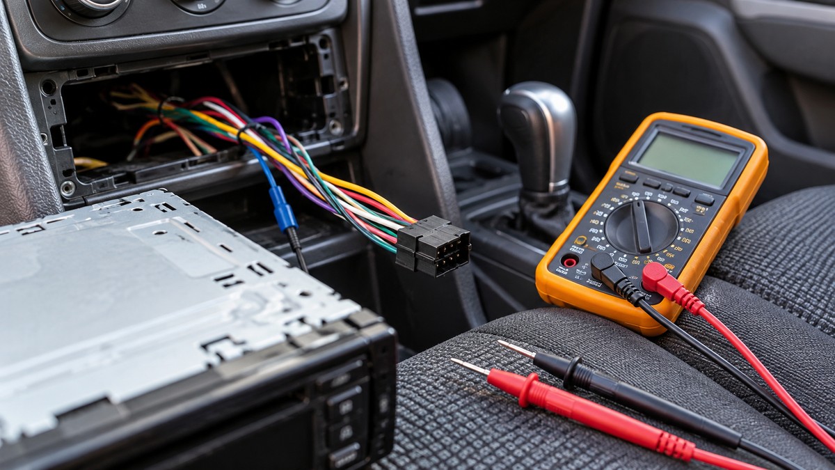
How to check a car stereo wiring with a multimeter means confirming three things at the head unit harness: a constant 12-volt feed, a switched 12-volt feed that appears only when the key is on, and a solid ground. After those, you check the speaker wires for shorts to the chassis. The steps below stay on 12-volt vehicle wiring and bench-style checks. They do not cover household outlets, panels or service wiring.
Electrical safety first
Work on mains circuits can kill. Before you measure anything, check that the meter’s CAT rating suits the circuit you are testing, and read the rating from the listing or the manufacturer’s manual. Panel and service work belongs to a licensed electrician.
The Fluke safety guide says that CAT ratings are used to match a meter to the electrical environment it will be used in. It advises choosing a tool rated for the highest category you could potentially use it in. For reference, the same guide gives an example of a CAT III-600 V meter for a 480 V distribution feeder panel. The sources do not say which CAT rating a car stereo harness requires, so the rating printed on your own meter or in its manual governs.
The Fluke guide also says the ratings are usually located near the input jacks. Check the probes and leads as well as the meter, because the leads can carry a different marking.
Quick answer
- Find the constant 12-volt wire first. It should stay at 12 volts with the key off.
- The switched wire carries 12 volts only with the key in the on or accessory position.
- A ground should read near zero ohms against the negative battery terminal.
- Disconnect speaker wires before any resistance test, then check each wire against chassis ground.
How we chose
This guide follows the order that the sources describe for a head unit. The radio installation guide from Retro Manufacturing lists three wires: yellow for 12-volt constant power, red for 12-volt ignition or accessory power, and black for ground. It says that if all three are not connected, the radio will not work.
The speaker and ground checks come from the Sweetwater and AudioIntensity speaker test guides, both of which describe disconnecting the speaker before measuring resistance, and from a car audio forum thread that describes measuring each speaker wire against chassis ground. The forum thread is a user account, not a manufacturer procedure, so the steps that rely on it are marked as such. The source set has ten pages: five Fluke pages, one Retro Manufacturing page, one Sweetwater page, one AudioIntensity page and two car audio forum threads. We did not compare products, prices or ratings, and this guide does not recommend any meter.
Preparation
Gather a digital multimeter with a DC volts setting, an ohms setting, and a continuity mode with an audible beep. You also need the head unit’s wiring diagram or the harness adapter labels, if you have them, and the vehicle’s fuse diagram. The Fluke automotive guide says to disconnect battery power or isolate the circuit before testing for continuity. The AudioIntensity guide adds that the battery should be disconnected before you test speaker resistance, because a live circuit can give false readings and can damage the meter.
Plug the black lead into the COM jack and the red lead into the jack marked V for voltage. The Fluke DC voltage guide says that when you measure DC voltage, you insert the red probe into the input jack marked V, not A. It adds that it is not critical for the red lead to contact a positive terminal, and that most modern multimeters detect polarity automatically. Set the dial to DC volts. The same page notes that modern meters default to autorange based on the function selected on the dial.
The Retro guide notes that not all factory radios have a 12-volt constant wire, and that you may need to test at the fuse box, cigarette lighter or ignition harness instead.
Step 1: Find the constant 12-volt wire
Connect the black lead to a clean metal point in the dash. The Retro guide says to secure the ground side of the meter to a good clean metal point in the dash, then probe the harness with the key off. Look for a wire that reads 12 volts DC. The Retro guide says you should find at least one wire carrying 12 volts at all times.
Next, turn the ignition on and then off. According to the Retro guide, there should be no change. Turn the headlights on and then off as well. If the wire stays at 12 volts, it is the correct constant wire, and the guide labels it yellow. If the reading drops or disappears, the wire is not a steady source.
Be careful with wires that happen to show 12 volts. A car audio forum user found that a yellow harness wire read 12 volts, then read lower after it was connected to the stereo, and noted that the wire could be a data wire. The same thread quotes a poster who says a can bus or data wire may read 12 volts but is not designed to be constant. The sources we opened do not say how to tell a data wire from a power wire with a meter, so confirm the wire on the vehicle’s wiring information before you connect a head unit to it.
Step 2: Find the switched accessory wire
With the key in the on or accessory position, probe the harness again with the black lead still on bare metal. The Retro guide says to look for at least one wire carrying 12 volts. Turn the key off and the voltage should go away. Turn the key back to accessory or run, and the voltage should return. That wire is the switched or ignition wire, which the guide labels red.
A forum poster in one car audio thread describes the same split: yellow is usually the constant feed and red goes to the accessory switch. The sources we opened do not give one color code for every vehicle, so use the color only as a starting point and let the meter confirm it.
Step 3: Check the ground
Set the meter to ohms. Touch one lead to the negative battery terminal and the other to the black wire, which the Retro guide describes as the ground wire. The guide says you should get a very low reading, around 0.1 or 0.3 ohms. Turn on the headlights and the ignition, and confirm that the reading does not change.
The Fluke automotive guide gives a related range for continuity checks on automotive wiring. It says a steady beep with a near-zero reading, about 0.0 to 0.2 ohms, indicates good continuity. It also says that when you test a ground, you should place one lead on bare engine block or chassis ground and the other on a component ground terminal or wire. If there is no continuity, the same guide says to suspect a broken ground strap or a corroded terminal.
The sources we opened do not give a pass-fail number for head unit grounds. A reading near zero matches both sources.
Step 4: Check the speaker wires for shorts to chassis
Disconnect the speaker wires from the head unit or amplifier before any resistance test. The Sweetwater guide says the speaker needs to be disconnected from the amplifier before testing, and the Fluke automotive guide says to avoid testing powered circuits in resistance mode. The AudioIntensity guide says to disconnect the speaker from any amplifier or battery before testing, because a live circuit can give false readings.
Next, measure between each speaker wire and chassis ground. A car audio forum thread describes this check: measure the resistance between each speaker wire and chassis ground, and if you read anything other than infinity, the terminals are shorted to chassis. This is a forum account, not a manufacturer instruction, so treat it as a practical check and confirm the wire routing against the vehicle’s documentation.
For a separate wire-tracing tool, read our automotive wire tracer guide. The AudioIntensity guide describes what the readings mean. It says that if you see 0 ohms, you have a short, and infinity means an open circuit. It says that a zero reading on a speaker coil is likely a burnt-out coil. In one of the car audio forum threads, an owner whose speakers measured 1.4 ohms suspected a terminal touching the door metal. That is the owner’s suspicion, not a finding from a manufacturer.
Step 5: Check the speaker resistance
With the speakers disconnected from the head unit, measure each speaker’s resistance across its own two terminals. The Sweetwater guide says that a 4-ohm speaker could measure between 2 and 3.4 ohms on a multimeter, an 8-ohm speaker between 5 and 7 ohms, and a 16-ohm speaker between 12 and 14 ohms. It also says that if a speaker measures very low or no resistance, it is bad, and that a very high resistance is also bad.
The car audio forum thread on 4-ohm speakers reports a case where the two working speakers read 4.0 ohms and the two that did not work read 1.4 ohms. This is one owner’s measurement and is shown for comparison only. The sources we opened do not say whether a 1.4-ohm reading on a 4-ohm speaker is always a fault in every system.
A speaker reading near its rated value does not prove the wiring is sound. The Sweetwater guide describes the resistance test as a check for a bad speaker, and the sources do not describe a resistance test for the full wiring harness beyond the steps above.
Step 6: Check the fuses
If the head unit shows no power, check the fuse before you test further. Fluke’s fuse guide says that continuity mode is generally preferred for fuse testing because it gives a clear, audible signal if the fuse is intact. Turn the meter on, select continuity, and touch the probes together to confirm the beep. Then place one probe on each end of the fuse, with firm, stable contact at the fuse terminals.
In continuity mode, a beep means the fuse is good and no beep means the fuse is blown. In resistance mode, a reading at or near zero means the fuse is intact, and an open-loop reading such as OL or 1 means it is blown. Fluke’s automotive guide says that for a removed fuse, power disconnection is not required. Fluke’s guide to continuity testing describes the beep as a response to a complete path,. For a wider set of continuity checks on wiring, see our wiring continuity test roundup.
Reading the results
A constant wire should read about 12 volts with the key off, and the reading should hold when the ignition and headlights switch. An accessory wire should read 12 volts only in the on or accessory position. A ground should read near zero ohms. The Retro guide gives about 0.1 to 0.3 ohms for its ground check, and the Fluke automotive guide gives 0.0 to 0.2 ohms for good continuity.
A speaker should read within the range the Sweetwater guide gives for its rated impedance. A reading of 0 ohms means a short, and a reading of infinity means an open circuit. A speaker wire that reads anything other than infinity to chassis, according to the forum method, points to a short to ground.
The sources do not give a voltage limit for every head unit. Read the operating voltage in the head unit’s own manual before you judge a reading as normal.
Common mistakes
- Testing a powered circuit in ohms or continuity mode. The Fluke automotive guide says to avoid testing powered circuits in continuity or resistance mode, because this can damage the meter.
- Assuming a wire is constant because it reads 12 volts once. The Retro guide says to turn the ignition and headlights on and off and confirm that the reading stays the same.
- Testing a speaker while it is still connected. The AudioIntensity guide says a live circuit can give false readings.
Frequently asked questions
Which wire is the constant 12-volt feed?
The Retro guide labels the constant feed yellow. It is the wire that stays at 12 volts with the key off, and it should not change when the ignition or headlights switch.
Which wire is the switched accessory feed?
The Retro guide labels the switched feed red. It carries 12 volts only when the key is in the accessory or on position.
Can I rely on wire colors alone?
No. The sources we opened do not give one color code for every vehicle. Use the meter to confirm each wire.
What does a beep mean in continuity mode?
The Fluke continuity guide says the meter beeps when it detects a complete path. The Fluke automotive guide gives a typical beep threshold of about 25 to 50 ohms, and it notes that the threshold varies with the meter.
What we could not verify
The sources we opened do not give a CAT rating for a car stereo harness, and this guide names no meter, so it does not state a CAT rating for one. The sources do not give a pass-fail ground resistance for every head unit, a color code for every vehicle, or a short-to-chassis procedure written by a car stereo manufacturer. The forum threads are user accounts, and they are cited only where the step is marked as such. The sources do not describe how to repair a wire, a connector or a door-related short. Read the head unit’s manual and the vehicle’s wiring information before you connect or change any wire.
Sources
- https://help.retromanufacturing.com/knowledge-base/wiring-your-radio/
- https://www.fluke.com/en-us/learn/blog/digital-multimeters/how-to-measure-dc-voltage-with-a-digital-multimeter
- https://www.fluke.com/en/learn/blog/digital-multimeters/how-to-test-for-continuity
- https://www.fluke.com/en-gb/learn/blog/digital-multimeters/how-to-perform-automotive-continuity-checks-with-a-multimeter
- https://www.fluke.com/en-us/learn/blog/digital-multimeters/how-to-check-fuse-with-multimeter
- https://www.fluke.com/en-us/learn/blog/safety/multimeter-guide
- https://www.sweetwater.com/sweetcare/articles/how-to-test-a-speaker/
- https://audiointensity.com/blogs/guides/how-to-test-speaker-with-multimeter-step-by-step-guide-for-accurate-audio-checks
- https://www.caraudio.com/threads/constant-power-at-12v-until-wired-to-head-unit-then-not-12v-stereo-doesnt-work.598435/
- https://www.caraudio.com/threads/4-ohm-speakers-measuring-0-5-ohms-before-crossover-what.552520/