How to Check a Car Audio Amplifier With a Multimeter
As an Amazon Associate we earn from qualifying purchases.
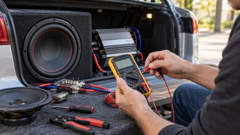
How to check a car audio amplifier with a multimeter follows a fixed order: confirm the fuse, measure 12-volt power at the amplifier, check the ground, check the remote turn-on lead, and only then test the speaker side. The sources below describe these checks on 12-volt vehicle systems, but they do not give one set of numbers for every amplifier, so your amplifier’s owner’s manual has the final word on its limits.
Quick answer
- Fuse first: check the battery-side fuse and any fuse built into the amplifier. A blown fuse gives no beep.
- Power next: expect about 12 volts at the amplifier with the engine off, and more than 14 volts with it running.
- Then ground and remote: confirm a bare-metal ground with the power off, and confirm about 12 volts on the remote lead with the radio on.
Electrical safety first
Work on mains circuits can kill. Before you measure anything, check that the meter’s CAT rating suits the circuit you are testing, and read that rating from the listing or the manufacturer’s manual. Panel and service work belongs to a licensed electrician. That last rule is this site’s own rule, not a finding from the sources.
Fluke’s safety guidance reports that a meter rated for 1000 volts, used on medium-voltage circuits, has ended in tragic results more than once. CAT ratings are overvoltage categories, and they tell you which electrical environments a meter is designed to handle safely. Fluke also says a meter must be rated for the circuit it is applied to, and that the rating should be printed on the tool itself.
If the listing does not state a CAT rating, the listing does not state a CAT rating, and you should not use that meter on any circuit this guide describes until you have the manufacturer’s figure. This guide covers only 12-volt vehicle wiring, fuses and bench checks on an amplifier. It does not describe steps on household outlets, breaker panels, service wiring or any circuit that carries mains power.
Preparation
Disconnect the negative battery cable before you add, remove or change any connection to the amplifier. The owner’s manual for the AL110.4 family lists this as its first preparation step. Reconnect the battery only for the live voltage check in step two. Fluke’s automotive continuity guide adds that power should be disconnected, or the circuit isolated, before any continuity test.
Gather a digital multimeter with a DC volts setting, a continuity mode with an audible beep, and an ohms setting. You will also need a fuse puller, a scraper for paint at the ground point, the amplifier’s manual, and a known good test speaker for the output check. Fluke’s battery guide sets the dial to VDC and offers a 6 V or 60 V range for batteries. One guide suggests a 20-volt DC range for amplifier checks. Our own assumption is that this range leaves room above a 12-volt system.
If you are still choosing a meter, our guide to a digital voltage meter for a car covers the basic functions. For the beep check in step one, the voltmeter continuity test guide explains what a beep means.
Step 1: Check the fuses
Start at the battery. The owner’s manual for the AL-series amplifiers says to check the in-line fuse on the battery’s positive cable and replace it if needed. The same manual says the fuse holder should sit within 18 inches of the battery. An installer guide places it within about six inches. The two figures disagree, so use the figure in your own amplifier’s manual.
Next, check any fuse built into the amplifier. The caraudiohelp troubleshooting guide says not to rely on a visual look. Remove the fuse with the amplifier off and test its continuity. A good fuse should read close to zero ohms.
Fluke’s fuse guide describes the result in two modes. In continuity mode, a beep means the fuse is good and no beep means it is blown. In resistance mode, a reading at or near zero means the fuse is intact, and an open-loop reading, shown as OL or 1 on many meters, means it is blown. Touch the probes firmly to the fuse terminals, because weak contact can give an incorrect reading. Fluke’s automotive guide says a removed fuse does not need the power disconnected for the test, but testing a powered circuit in continuity or resistance mode can damage the meter.
Replace a blown fuse only with one of the same rating. An installer guide warns that a higher-rated fuse can damage the amplifier.
Step 2: Measure power at the amplifier
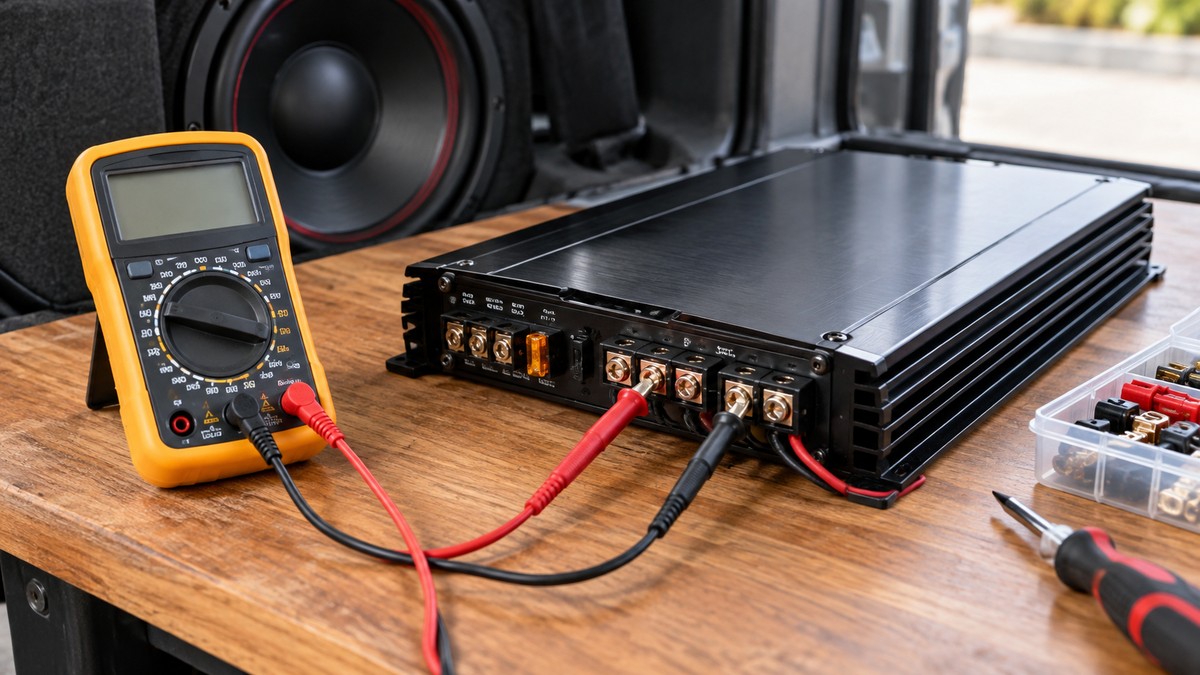
Set the meter to DC volts. Fluke’s DC voltage guide says the red probe belongs in the jack marked V, not the one marked A. Touch the black lead to the amplifier’s ground terminal and the red lead to the power terminal labeled B+ or +12 V.
With the engine off, expect about 12 volts. The caraudiohelp guide gives about 12 volts engine off and more than 14 volts with the engine running. The electricnerds guide gives about 12 to 14.4 volts for engine off and on. The two agree at 12 volts but differ at the top, so treat the running figure as a range.
The owner’s manual we opened gives an operating window of 8.5 to 16 volts for the AL-series models. Voltage above 16 volts puts those models into protect mode. A reading below 8.5 volts is the point to stop and check the wiring.
If the reading is low or missing, the caraudiohelp guide says to check the power and ground wires at every point where they could loosen, including the ground bolt, the fuse block and the battery connection. The electricnerds guide also says to check voltage at the amplifier’s own power and remote terminals.
Step 3: Check the ground
With the battery disconnected, set the meter to continuity or to the lowest ohms range. Place one probe on the amplifier’s GND terminal and the other on bare chassis metal. The electricnerds guide says the metal should be bare, not painted. A steady beep, or a reading near zero, shows a good path. Fluke’s automotive guide puts a good reading at roughly 0 to 0.2 ohms.
The manual asks for a clean location with a direct electrical connection to the vehicle chassis, and it limits the ground cable to 3 feet. The big5 installer guide says to scrape paint from the contact point so the joint is bare metal to bare metal, and it calls improper or loose grounding the most common cause of amplifier problems.
Continuity measures resistance, not voltage. Fluke’s guide notes that low resistance does not prove that voltage is present, and the electricnerds guide lists testing continuity with the power on as a beginner mistake.
Step 4: Check the remote turn-on lead
On an aftermarket head unit, the true remote output is usually the blue wire with a white stripe. The solid blue wire is usually the power-antenna lead, and it can shut the amplifier off when the source is not the radio. The improvecaraudio guide describes this split, and the caraudiohelp guide notes that wire colors can vary, so check the head unit’s manual.
Turn the head unit on with a source other than the radio, then measure from the amplifier’s REM terminal to ground. The caraudiohelp guide expects about 12 volts. The improvecaraudio guide adds the second half of the check: with the radio on, REM should show about 12 volts, and it should drop back to 0 volts shortly after the radio is turned off.
If there is no voltage on any source, the caraudiohelp guide says the remote lead is not working, so check its connections and the small fuse in that lead at the head unit. If voltage appears only on the radio source, the solid blue antenna lead may be wired to the amplifier in place of the true remote lead.
Two wiring choices are off limits in these guides. The improvecaraudio guide says never to use a constant 12-volt feed for the remote, and never to tap airbag, SRS, CAN or other data wiring for the amplifier trigger. This guide follows both rules.
Step 5: Test the speaker side
Turn the system off and disconnect the speaker wiring from the amplifier. The caraudiohelp guide then connects a known good test speaker to one channel at a time. If the test speaker plays on every channel, the fault is after the amplifier. If the amplifier turns on but the test speaker stays silent, the amplifier is the suspect.
For a quick resistance check, set the meter to continuity or the lowest ohms range and test between the speaker output terminals, with the amplifier off and the speaker wires removed. The electricnerds guide describes this check. The sources we opened do not say how a meter reading compares with a speaker’s rated impedance, so this guide gives no target value.
Stray wire strands are a common cause of trouble here. The big5 guide says it is common to find a strand or two of stray wire touching another wire. When that happens, none of the speakers work, because the amplifier senses a short and shuts down.
Reading the results
A power reading of about 12 volts with the engine off, and a bit above 14 volts with the engine running, matches the guides above. A reading above 16 volts on the AL-series models is outside the manual’s window. A low or missing reading points back to the fuse, the battery connection, or the power and ground wires.
When the protect light is on, the manual lists three possible causes: a connected load below the specified impedance, overheating, and a short circuit. Disconnect the speakers first and see whether protect clears. If it stays on with the speakers removed, work back through the power, ground and remote checks above.
Common mistakes
- Testing continuity with the power on. Both the Fluke guide and the electricnerds guide warn against it.
- Making a ground connection on painted metal. The electricnerds and big5 guides both call for bare metal.
- Using a constant 12-volt feed or a data wire as the remote trigger. The improvecaraudio guide rules out both.
- Confusing the solid blue antenna lead with the true remote lead. The improvecaraudio and caraudiohelp guides both describe the difference.
How we chose
A step made it into this guide only when a page we opened on 2026-10-21 described that procedure and could be read as text. Numbers come from the owner’s manual or from more than one page, and where pages disagree both figures are shown. We did not use retailer pages for procedure, and we did not use pages that returned 403 or 429. We opened 17 pages with readable text and used 11 of them. The other six were not needed for any step, or their figures did not match the other sources. This guide does not rank products, compare prices, or recommend a meter or an amplifier.
What we could not verify
- The sources do not give a remote turn-on threshold for every amplifier. The manual gives an operating window only for its own models.
- The running-voltage figures differ, at about 14 volts in one guide and up to 14.4 volts in another.
- The fuse distance from the battery differs: 18 inches in the manual and about six inches in the installer guide.
- No source we opened gives a resistance limit for a good amplifier ground.
- No source we opened explains how a meter reading compares with a speaker’s rated impedance.
- The listing does not state a CAT rating for any meter, and this guide names no meter.
- The sources do not cover the internal parts of an amplifier, so this guide stops at the terminals and the speaker output.
FAQ
Can I check the amplifier while it is still installed? Yes, for the power, ground, remote and output checks. The electricnerds guide says only internal component testing or a suspected short calls for removing the amplifier.
Does a beep prove the amplifier works? No. A beep shows a low-resistance path, which Fluke’s guide distinguishes from voltage being present. It does not show that the amplifier is delivering sound.
What if the remote lead reads 0 volts with the radio on? Check the connections and the small remote fuse at the head unit first. If the lead shows voltage only on the radio source, you may be on the antenna lead.
Can I use a larger fuse if the old one keeps blowing? The sources say no. One installer guide warns that a higher rating can damage the amplifier, and the manual says the fuse and holder must suit the application. Find out why the fuse is blowing first.
When should I contact the manufacturer? When the power, ground, remote and fuse checks all pass and the amplifier still gives no output, the caraudiohelp guide advises contacting the manufacturer first, especially under warranty.
Sources
- Fluke, How to Measure DC Voltage with a Digital Multimeter: https://www.fluke.com/en-us/learn/blog/digital-multimeters/how-to-measure-dc-voltage-with-a-digital-multimeter
- Fluke, How to Measure Battery Voltage with a Multimeter: https://www.fluke.com/en-us/learn/blog/digital-multimeters/how-to-test-a-battery-with-a-multimeter
- Fluke, How to Check a Fuse with a Multimeter: https://www.fluke.com/en-us/learn/blog/digital-multimeters/how-to-check-fuse-with-multimeter
- Fluke, How to Perform Automotive Continuity Checks with a Multimeter: https://www.fluke.com/en-us/learn/blog/digital-multimeters/how-to-perform-automotive-continuity-checks-with-a-multimeter
- Fluke, safety guide on how to go home safely at the end of the day: https://www.fluke.com/en-us/learn/blog/safety/how-to-go-home-safely-at-the-end-of-the-day
- tester.co.uk, What Are CAT Ratings: https://tester.co.uk/advice/what-are-cat-ratings
- Owner’s Manual for AL110.4, AL700.1D, AL1200.1D and AL1600.1D: https://cdn.shopify.com/s/files/1/0239/1493/8448/files/Manual_for_AL110.4_AL700.1D_AL1200.1D_AL1600.1D.pdf?768
- Car Audio Help, Car Audio Amplifier Troubleshooting: https://www.caraudiohelp.com/newsletter/car_amp_troubleshooting.html
- Electric Nerds, How to Test a Car Amp With a Multimeter: https://electricnerds.com/how-to-test-a-car-amp-with-a-multimeter/
- Improve Car Audio, Where to Connect the Remote Wire for a Car Amp: https://improvecaraudio.com/where-to-connect-remote-wire-for-car-amp/
- Big 5 Electronics, Amplifier Installation Guide: https://big5electronics.com/newsroom/amplifier-installation-guide/