How to Choose a Multimeter for Measuring Inductance
As an Amazon Associate we earn from qualifying purchases.
How to choose a multimeter for measuring inductance comes down to one check first: does the meter have an inductance (L) mode, and does its range cover the value you expect? Most handheld multimeters are not described as inductance meters, and the sources we opened say a dedicated inductance or LCR meter is usually the better tool. This guide explains what to check on a listing or manual, what the sources say about test conditions, and which low-voltage bench methods exist when a meter has no L mode. It does not cover live mains, panels, outlets or service wiring.
Quick answer
- Measure only parts that are disconnected from any circuit. Mains can kill.
- Check the manual or listing for an L mode, and confirm that its range covers the value you need.
- Confirm the CAT rating of the meter and its test leads before you connect anything.
- Match the test frequency and level to the datasheet, because readings change with both.
Electrical safety
Work on mains circuits can kill. The UK Health and Safety Executive states that electricity can kill or severely injure people, and that normal mains voltage, 230 volts AC, can kill. Measure only parts that are disconnected from any circuit, and keep the meter away from live conductors.
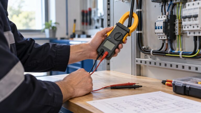
Before you measure anything, check that the meter’s CAT rating suits the circuit you are testing, and read the rating from the listing or the manufacturer’s manual. The Klein MM400 manual says never to use the meter on a circuit with voltages that exceed the category rating, and that failure to observe its warnings can result in severe injury or death. A Fluke safety sheet says not to exceed the CAT rating of the lowest rated individual component of a product, probe, or accessory, so test leads count too.
Panel and service work belongs to a competent person, such as a licensed electrician. The HSE describes a competent person as someone with suitable training, skill, and knowledge for the task.
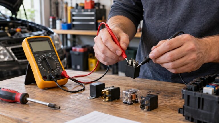
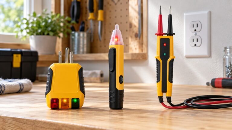
For a quick check before you touch any wire, see the non-contact voltage detector guide. This guide gives no steps for live mains, panels, outlets or service wiring. The methods below are low-voltage bench methods for components such as inductors and coils. Voltage rating, counts, maximum current and fuse ratings come only from a listing or a manufacturer manual. Where those sources do not state a value, this post says so.
How we chose
The sources were chosen because they describe an inductance function in a meter manual or review, give a test condition, range or formula that can be checked, or state a safety rule for handheld meters. Pages that returned 401, 403, 404, or timed out were not counted. Retailer listings were used only for listing facts. The forum threads and the LCR vendor blog are cited only for the points they state. Every quote was matched against the fetched page text, and the sources were opened on 2026-10-21.
What to check on a listing or manual
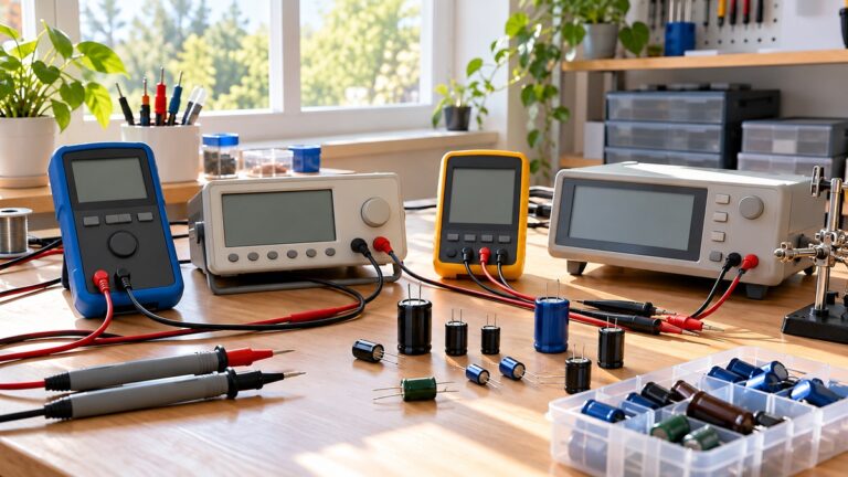
Start with the function list. An inductance reading needs an L mode. The Elektor review of the UNI-T UT603 describes an L mode with five separate ranges that must be chosen manually on the rotary switch, running from 20 H down to 2 mH. The same review says the smallest range has a resolution of 0.001 mH, or 1 µH. That is one model, and the review does not say whether other handheld meters have a similar mode.
Next, compare the range with the value you expect. The same review says the UT603 has limited ranges, which makes it less suitable for very small or very large values of inductance. For automatic ranging on other functions, see the auto-ranging digital multimeter guide.
Check the CAT rating and the test leads. The Klein MM400 manual states CAT III 600V and says to use only CAT III or CAT IV rated test leads. The MM400 is not an inductance meter. Its manual lists AC/DC voltage, AC/DC current, resistance, temperature, capacitance, frequency, duty cycle, diode test, and continuity, and it does not list inductance. The EX330 listing page we opened does not mention inductance either, so a meter with a different name can still lack the function.
Look for a test frequency and test level in the manual. The sources do not state either for the UT603 L mode. The LCR vendor guide explains why this matters: a 10 µH inductor can look entirely different at 1 kHz and 100 kHz, and the core permeability changes with frequency, AC excitation level, temperature, and DC bias. If the manual does not give a test frequency, the reading can still be useful for sorting parts, but it should not be treated as a direct check against a datasheet.
Finally, decide whether a dedicated meter is needed. The Wikipedia multimeter article says inductance in henries is a function that is usually better handled by a purpose designed inductance or capacitance meter. The electrical impedance article notes that an LCR meter measures inductance, capacitance and resistance, and that impedance at any frequency can be calculated from those values. For a dedicated instrument, see the LCR meter guide.
Methods when the meter has no L mode
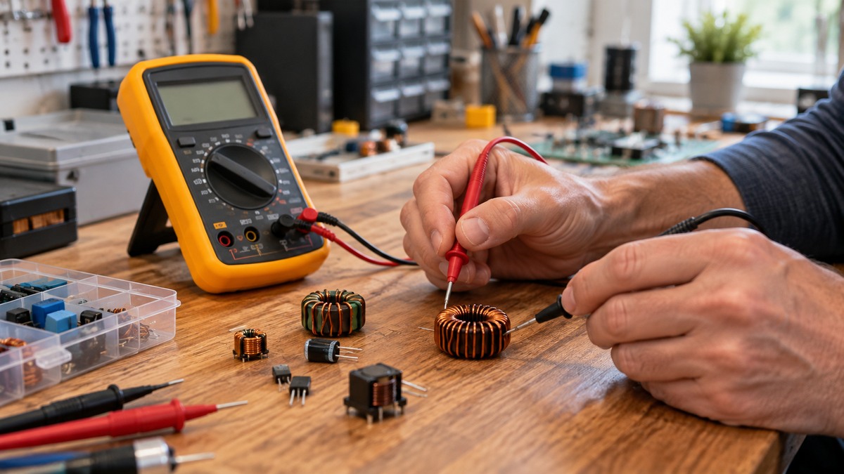
Many multimeters have no L mode. The Daycounter tutorial says most multimeters measure every electrical property of a component with the exception of inductance, and it describes three bench methods. Each method needs equipment beyond a multimeter, usually a function generator and an oscilloscope. Each assumes the inductor is disconnected from its circuit.
Method 1: series resistor. Place the inductor in series with a known precision resistor. The Daycounter example uses a 100 ohm 1% resistor. Drive the circuit with a function generator, view the voltage at the junction on a scope, and tune the generator until the junction voltage is half the input voltage. The page gives L = R/(2πf√3), where f is the frequency at that point. The same page says calibration resistors can be found with tolerances in the 0.1% range, which is why this method is described as accurate.
Method 2: resonance with a known capacitor. Place the coil in parallel with a capacitor of known value to form a tank circuit, then place that tank in series with a resistor of reasonable value. Drive the circuit with a function generator and sweep the frequency while watching the response on a scope. The peak is the resonant point. The Daycounter page gives L = 1/((2πf)²C), and the standard LC resonance relation is ω0 = 1/√(LC), where ω is angular frequency and equals 2π times the frequency in hertz. The same page notes that reference capacitors with tolerances below 10% are harder to find, which limits accuracy.
Method 3: voltage and current slope. Apply a pulsed voltage across the inductor and monitor the current through a sense resistor or a current probe. The Daycounter page gives L = V·Ton/Ipk, where Ton is the on time and Ipk is the peak current, and it says the pulse duty cycle should be below 50% and the frequency should be high enough to avoid core saturation. This is the most complex of the three methods, and the page calls it so.
A published design for a resonance-based inductance meter is available from the University of Georgia. The PDF we opened is titled Low-Inductance, Resonance-Based Inductance Meter and carries a 2023-24 copyright. The sources we opened show only its schematic text, so this post does not describe its accuracy or how it is calibrated.
Setting up a meter that has an L mode
Follow your model’s manual first. The steps below follow the sources and do not replace it.
- Power down and disconnect the inductor. The Siborg guide warns that an inductance reading can be wrong when a nearby circuit path is still connected. Remove the part from its circuit before you connect the leads.
- Select the range manually. On the UT603 the L ranges are chosen on the rotary switch, not automatically, according to the Elektor review. The sources we opened do not give a rule for choosing a starting range when the value is unknown. Starting on a higher range is an assumption of this post, not a sourced step.
- Keep the leads short and secure. The Siborg guide says long leads add impedance, which can distort a reading of a small inductor. Its compensation steps, described for LCR meters, are open and short compensation at the probe tips. The sources we opened do not describe lead compensation for a handheld L mode.
- Record the test condition with the reading. If the meter displays a frequency or level, write it down beside the value.
- Compare with the datasheet, not the distributor. In one DigiKey forum thread, a user asked about an inductor whose datasheet specified 100 kHz and 250 mV while the distributor listing showed 1 kHz. The forum reply says the manufacturer’s product specifications should be considered authoritative.
The Siborg guide gives the datasheet condition for a typical power inductor as 100 kHz, 0.1 V RMS, and zero DC bias. A datasheet for a different part may state other conditions, so check the condition for your part before you compare readings.
Reading the result
A reading that matches the marking is a useful check only when the test condition matches the datasheet. The Siborg guide says a power inductor specified at 10 µH at 100 kHz may not give the same displayed value at 1 kHz. A high AC test level can push a ferrite core toward saturation and give a lower apparent inductance, which the guide says is especially relevant for ferrite power inductors and current-sense chokes.
The Wikipedia inductor article defines the quality factor, Q, as the ratio of inductive reactance to resistance at a given frequency. A higher Q means the inductor behaves more like an ideal inductor. The sources we opened do not give a Q threshold that separates a good part from a bad one.
The sources do not give a pass or fail tolerance for any meter’s L mode.
Common mistakes
- Measuring while the part is still connected. A nearby circuit path can change the reading, according to the Siborg guide. Disconnect the part first.
- Trusting one number at any frequency. Inductance changes with test frequency and level, so a single value is only comparable when the condition is known.
- Using the wrong range. The UT603 ranges are chosen by hand, and its range limits make very small or very large values less suitable for that meter, per the Elektor review.
- Driving a magnetic core hard. The Siborg guide warns that a high test level can shift a core into a nonlinear region.
- Ignoring the lead rating. The Fluke safety sheet says the lowest rated component sets the limit, so a probe or lead with a lower CAT rating limits the whole setup.
- Measuring on live circuits. The Klein MM400 manual says not to measure resistance or continuity on a live circuit. The sources we opened do not describe inductance measurement on a live circuit, so treat the inductor as off-limits until it is disconnected.
Frequently asked questions
Can a standard multimeter measure inductance?
Some can, and many cannot. The Daycounter tutorial says most multimeters do not measure inductance. The Elektor review describes a meter that has an L mode. The sources we opened do not list which models have one, so check the manual before you rely on a meter. For capacitance readings, the capacitor meter guide covers a related function.
What range should I select?
Choose the range that covers the value you expect, and set it on the meter by hand where the model requires that. The Elektor review gives the UT603 ranges, but the sources do not give a rule for an unknown value.
Do I need an LCR meter?
For precise work, the sources suggest a dedicated meter. Wikipedia says inductance is usually better handled by a purpose designed meter, and the Siborg guide explains that readings depend on frequency and level.
Is it safe to measure an inductor in a mains device?
Not without isolating the part first. Leave mains, panel and service work to a competent person, as the HSE recommends for fixed installations, and keep every measurement on a part that is off its circuit.
Which test condition should I use?
Use the condition printed on the datasheet for your part. The Siborg guide gives 100 kHz, 0.1 V RMS and zero DC bias as an example of a datasheet condition, not a rule for every inductor.
What we could not verify
The sources we opened do not state the test frequency, test level, or accuracy of any handheld multimeter’s L mode. The UT603 ranges come from one Elektor review, because the TME product page returned 403 and could not be opened. The listing does not state a CAT rating for the UT603 in any page we opened.
No Fluke or Klein manual we opened lists an inductance function. The Fluke 117 manual copy hosted by UCL and the Klein MM400 manual do not list inductance, and the EX330 listing does not mention it.
The sources do not say how a handheld L mode compensates for leads, what its test frequency is, or whether it is safe on an energized circuit. The sources also do not give a pass or fail tolerance for an inductor, and the UGA meter design has no accuracy figure in the pages we opened.
Sources
- https://en.wikipedia.org/wiki/Multimeter (opened 2026-10-21)
- https://en.wikipedia.org/wiki/Inductor (opened 2026-10-21)
- https://en.wikipedia.org/wiki/LC_circuit (opened 2026-10-21)
- https://en.wikipedia.org/wiki/Electrical_impedance (opened 2026-10-21)
- https://daycounter.com/Articles/How-To-Measure-Inductance (opened 2026-10-21)
- https://elektormagazine.com/review/lcr-meter-the-uni-t-ut603-review (opened 2026-10-21)
- https://photonics.engr.uga.edu/inductor_meter/inductance_meter.pdf (opened 2026-10-21)
- https://siborg.com/?p=159 (opened 2026-10-21)
- https://forum.digikey.com/t/74477020-test-conditions/66998 (opened 2026-10-21)
- https://www.eoas.ubc.ca/courses/atsc303/Instruments/manuals/0_Klein-Tools-MultiMeter-MM400-UsersManual.pdf (opened 2026-10-21)
- https://intranet.ee.ucl.ac.uk/facilities/teaching-lab/flukedmm.pdf (opened 2026-10-21)
- https://www.hse.gov.uk/pubns/indg231.pdf (opened 2026-10-21)
- https://assets.testequity.com/te1/Documents/pdf/fluke/Fluke_377378-SafetySheet.pdf (opened 2026-10-21)
- https://assets.testequity.com/te1/Documents/pdf/fluke/Fluke_8x__sseng0100_0625.pdf (opened 2026-10-21)
- https://www.extech.com/products/EX330 (opened 2026-10-21)