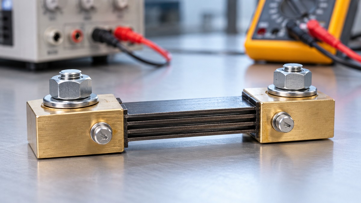
What Is a Current Shunt
As an Amazon Associate we earn from qualifying purchases.
What is a current shunt? It is a low-value resistor that a multimeter places in the current path when it measures current. The meter reads the small voltage that the current produces across the shunt and converts that reading into amps or milliamps. This explainer covers the shunt’s role in a meter’s current ranges, the burden voltage and internal fuse that come with it, and why a current jack must never be connected across a voltage source.
Electrical safety
Mains circuits can kill, and a current range does not make a meter suitable for them. Before any connection, compare the meter’s CAT rating with the category of the circuit, using the listing or the manual for that model. A licensed electrician should handle panel and service jobs. This explainer gives no steps for live mains, outlets, panels or service wiring.
The hazard reaches beyond mains. East Texas A&M University’s electrical safety page states that electrical hazards can cause serious injuries or death, and it warns that low voltage does not mean low hazard. IAEI Magazine’s piece on shock rescue notes that even household currents can be deadly. Fluke’s safety guide says shock occurs when the human body becomes part of an electrical circuit, and it asks readers to check CAT ratings for their environment.
A current range adds a hazard of its own. Its input has very low resistance, so a voltage source connected across it can push a large current through the meter, blow the fuse and damage the leads. The Klein MM400 manual warns that failure to observe its warnings can result in severe injury or death. The LabsLand lesson, a remote-lab exercise aimed at first-year university electronics, states plainly that a current input has very low resistance.
Cornell Law School’s text of the OSHA electrical work-practice rule says that “only qualified persons may work on electric circuit parts” that have not been deenergized. The licensed-electrician requirement above is a site policy, and it goes further than that text.
Quick answer
- A current shunt is a low-value resistor in series with the measured current. The meter reads the voltage across it.
- That voltage is the burden voltage. It lowers the voltage the circuit receives, and the effect is largest on low-voltage sources.
- Current inputs carry internal fuses. The Klein MM400 manual lists 500 mA and 10 A fuses for its current inputs.
- A current jack must not be connected across a voltage source. Fluke’s manual and two knowledge-base articles name this risk.
What a current shunt is
A shunt is a resistor of known, low value that sits in the path the measured current must take. The Berea College introductory physics text describes an ammeter as a galvanometer with a small shunt resistor in parallel, so that most of the current passes through the shunt rather than the sensitive coil.
A digital meter follows the same idea, with an electronic voltmeter circuit in place of the coil. Keithley’s application note describes meters for ordinary currents as a voltmeter circuit that measures the voltage drop across a shunt resistor in series with the circuit under test. Keysight’s note makes the error side explicit: when a multimeter is connected in series, a voltage develops across its wiring resistance and its current shunt resistance.
Each current input has its own shunt value
A multimeter usually has several current inputs, and each has its own shunt. The Fluke 27 manual gives approximate terminal resistances of 0.1 ohms for its A input, 5.6 ohms for mA and 500 ohms for µA. Our own assumption, for arithmetic only: at 100 mA, the A input would drop 0.01 V, while the mA input would drop 0.56 V. The same current gives a very different voltage on each input. For models with milliamp inputs, see a roundup of milliamp meters.
How the meter reads the shunt voltage
Three things happen inside the meter. The measured current flows through the shunt. An input circuit measures the voltage across the shunt. Because the resistance is fixed and known, the voltage follows the current, and the reading is scaled to amps or milliamps. Keithley’s note puts the result directly: the voltmeter reading is directly proportional to the current flow.
Ohm’s law gives the arithmetic. Voltage equals current times resistance, so 1 A through 0.1 ohm produces 0.1 V, and dividing that voltage by the same resistance returns 1 A (our own assumption, arithmetic only). The Klein MM400 manual says the meter auto-ranges to display the measurement in the most appropriate range. The sources we opened do not describe the internal circuit of any particular model, so its switching method is not described here.
Why current ranges have a burden voltage
The Fluke 27 manual defines the term: the voltage developed across the terminal resistance is specified as burden voltage. Every current range has one, because the shunt sits in the current path. The burden lowers the voltage available to the circuit, so it can lower the current the circuit would carry without the meter.
Fluke’s article “Can you live with the burden?” calls burden voltage a little used specification in the user manual. It explains that inserting the A or mA input in series with a current loop can significantly reduce the actual current flowing in the circuit. The article compares the burden with the supply voltage to judge the error. A high-voltage loop sees little effect, while a loop powered by two AA batteries, about 3 V, can see a significant one.
Size and frequency of the error
Keysight expresses the error as 100 times the burden voltage divided by the source voltage. A 0.1 V burden on a 3 V source gives about 3.3 percent, and on a 12 V source about 0.8 percent (our own assumption, arithmetic only). Keysight also states that the burden voltage increases as the input frequency increases, and that it is larger for AC current because of the meter’s series inductance and the measurement connections.
Typical figures
Keithley’s note gives a general range of usually 200mV to about 2V for the voltage burden of shunt-type meters. It also says that at normal currents, typically above 1 mA, burden errors are often small enough to be ignored. Those are class figures, not a rating for any named multimeter.
Why current ranges have an internal fuse
A current range can receive more current than its input is built to carry, and the fuse is there to open before that overload damages the input. The Fluke 27 manual says all its current ranges are fuse protected. It also says to install only the exact replacement fuse, to prevent arc blast and resulting injury.
The Klein MM400 manual gives its overload protection as 500 mA / 600 V and 10 A / 600 V fuses. It warns that a fuse may blow if more than 500 mA is applied to the VΩ jack, or more than 10 A to the 10 A jack. It assigns catalog 69033 to the VΩ, µA and mA jack and catalog 69032 to the 10 A jack. Klein’s product page for 69033 calls it a fast-acting ceramic fuse that reduces the possibility of internal arc flashes.
Our own assumption, for explanation only: the fuse is the part that gives way first in an overload. The sources do not give the time a fuse takes to open, so this explainer states no figure for it.
Why the current jacks must not be used across a voltage source
The LabsLand lesson states that a current input placed directly across a power supply can create a near-short circuit, blow the meter fuse, damage leads, or stress the supply. It calls this one of the most important first-lab safety rules.
The Fluke 27 manual states the rule as a warning: never touch the probe to a voltage source when the test leads are plugged into the 10 A or 40 mA input jacks. Two Fluke knowledge-base articles, on the 87V and the 87, describe the same failure. A lead in a current jack, with the other lead in the common jack, followed by a voltage measurement, blows the fuse and can damage the meter.
Our own assumption, arithmetic only: using the 0.1 ohm A-input figure as an illustration, a 3 V source across that path would drive about 30 A, three times the 10 A maximum in the Klein MM400 manual. The real current depends on the source, the leads and the meter.
Jack choice matters too. The Klein manual sends the red lead to the 10 A jack for currents above 400 mA and to the VΩ jack for milliamp currents, and the two jacks carry different overload limits. For a comparison with a different way of measuring current, see a side-by-side comparison of clamp meters and multimeters.
Common mistakes
- Connecting a current jack across a voltage source. Fluke’s manual and both knowledge-base articles name this as the cause of a blown fuse and possible damage.
- Treating every current input as the same. The Fluke 27 manual gives different terminal resistances for its A, mA and µA inputs.
- Ignoring burden in a low-voltage loop. The Keysight formula gives a larger error when the source voltage is smaller.
- Replacing a fuse with the wrong part. The Fluke 27 manual says to use only the exact replacement, and the Klein manual lists separate 500 mA and 10 A parts.
- Choosing the jack by habit. The Klein manual assigns the 10 A jack to currents above 400 mA and the VΩ jack to milliamp currents.
FAQ
Is a current shunt the same thing as a fuse?
No. The shunt sets the voltage the meter reads for a given current, and the fuse opens when the current exceeds the input’s limit. The Fluke 27 manual lists terminal resistance and fuse protection as separate facts.
Why does the same current give different voltages on different inputs?
Each input has its own terminal resistance. Voltage equals current times resistance, so the higher resistance gives the larger voltage at the same current. The Fluke 27 manual gives 0.1 ohms for A and 5.6 ohms for mA.
Can I use a current jack to check a battery’s voltage?
No. The Klein manual places the red lead in the VΩ jack for voltage measurements. A current jack across a voltage source is the failure that the Fluke 27 manual and the Fluke knowledge-base articles warn about.
Does a low burden voltage make a current jack safe on mains?
No. A low burden voltage describes the drop across the input, not the category of the circuit. The Klein MM400 manual warns never to use the meter on a circuit whose voltage exceeds the category-based rating of the meter. The sources do not treat any current range as mains-safe.
Which manual gives the figures for a particular meter?
Read the manual for that exact model. The Fluke 27 and Klein MM400 figures here apply only to those two meters. Models with DC current ranges are compared in a roundup of DC current meters.
How we chose
Three purposes guided the choice of sources: explaining how a shunt works, giving figures that a named manufacturer or manual states, and supporting the safety statements. Manuals and application notes ranked highest, since a model’s figure carries weight only when its maker publishes it. An education source covered the principle and the current-input hazard. Safety statements came from a university page, a professional association article and the text of a federal regulation.
Each source was fetched with curl on 2026-10-22; a source counted only with an HTTP 200 response and readable text. Five candidates were excluded: a Keysight white paper and an All About Circuits page returned HTTP 403, a JoVE page returned an empty HTTP 202, an Indian e-book host could not be reached, and a university course PDF could not be resolved by name. Search results only helped locate addresses. No retailer listing, forum thread or user-uploaded slide deck supports any claim here. Figures for named meters come only from those meters’ own manuals. Three documents are hosted by third parties at xdevs.com, and the Klein MM400 manual is a copy hosted by the University of British Columbia. Before use, each quotation was matched against the saved text of its page.
What we could not verify
The points below fall outside what the sources we opened cover, so this explainer leaves them open rather than estimating.
- The internal layout of any current input, including the shunt construction, the switching method and each model’s tolerance.
- Burden figures for named models other than the Fluke 27 and Klein MM400. The Keysight white paper returned HTTP 403, so per-range figures for newer Keysight meters are not in this explainer.
- Fuse ratings beyond the two manuals named here. The Fluke 27 specification table is garbled in the copy we opened, so its fuse values are not stated.
- Fault currents at a real installation, and the time a given fuse takes to open. No page we opened gives either figure.
- Whether the licensed-electrician requirement applies in a given place. The Cornell copy of the rule covers only the qualified-person point.
- Which instruments the Keithley range of 200mV to about 2V covers beyond the general class. The note gives the range without a model list.
- Whether a meter’s category carries over to separately sold test leads. The Klein manual requires CAT III or CAT IV rated leads, but gives no lead rating for any model.
In plain words: the sources we opened give no shunt value, fuse rating or burden figure for any multimeter beyond the two manuals named here, and they do not say how fast a fuse opens. Check the manual for the model you own before relying on any number.
Sources
- Fluke, “Can you live with the burden?”: https://www.fluke.com/en-us/learn/blog/electrical/can-you-live-with-the-burden
- Fluke knowledge base, KA-03156 (Fluke 87V input alert): https://my.fluke.com/en-us/article/KA-03156
- Fluke knowledge base, KA-03278 (Fluke 87 input alert): https://my.fluke.com/en-us/article/KA-03278
- Fluke, “Guide to digital multimeter safety”: https://fluke.com/en-us/learn/blog/safety/multimeter-guide
- Fluke 27 user manual, copy hosted at xdevs.com: https://xdevs.com/doc/Fluke/27/FLUKE%2027%20User.pdf
- Keysight application note 5988-5512, DC and AC current errors, copy hosted at xdevs.com: https://xdevs.com/doc/HP_Agilent_Keysight/Resistance%3B%20DC%20Current%3B%20AC%20Current%3B%20and%20Frequency%20and%20Period%20Measurement%20Errors%20in%20DMMs%205988-5512EN%20%5B4%5D.pdf
- Keithley application note, low current measurements, copy hosted at xdevs.com: https://xdevs.com/doc/Keithley/Appnotes/LowCurtMsmntsAppNote.pdf
- Klein Tools MM400 instruction manual, copy hosted by the University of British Columbia: https://www.eoas.ubc.ca/courses/atsc303/Instruments/manuals/0_Klein-Tools-MultiMeter-MM400-UsersManual.pdf
- Klein Tools, product page for replacement fuse catalog 69033: https://kleintools.com/product/69033
- Berea College, introductory physics, “20.4 Measuring current and voltage” (LibreTexts): https://phys.libretexts.org/Courses/Berea_College/Introductory_Physics%3A_Berea_College/20%3A_Electric_Circuits/20.04%3A_Measuring_current_and_voltage
- LabsLand Teach, “Electronics Lab Essentials (4/7): measure current without creating a short circuit”: https://teach.labsland.com/en/lessons/electronics-lab-essentials-4-7-measure-current-without-creating-a-short-circuit/
- East Texas A&M University, Electrical Safety: https://www.etamu.edu/electrical-safety/
- IAEI Magazine, “Safe Rescue From Electric Shock”: https://iaeimagazine.org/electrical-safety/safe-rescue-from-electric-shock/
- Cornell Legal Information Institute, 29 CFR 1910.333 (OSHA text): https://www.law.cornell.edu/cfr/text/29/1910.333