How to Check Dash Camera Wiring With a Multimeter
As an Amazon Associate we earn from qualifying purchases.
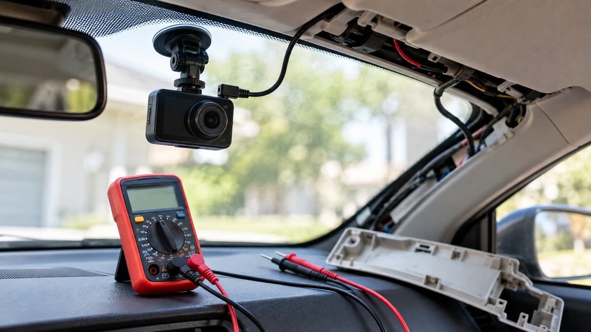
How to check a dash camera wiring with a multimeter comes down to three checks before you trust a hardwire installation: the constant fuse has power with the car off, the ACC fuse has power only when the key is in accessory or on, and the ground wire makes a solid connection to bare metal. This guide covers 12-volt vehicle wiring only. It does not cover mains outlets, household wiring, or any airbag or high-voltage system.
Quick answer
- Find the constant fuse with the ignition off and the ACC fuse with the key in accessory.
- Check the ground screw in continuity mode, and look for bare metal.
- Set the cutoff from your kit’s manual, then run the power-on test.
- Do not connect the kit to airbag, horn, or stability fuses.
Electrical safety
Work on mains circuits can kill. This guide does not describe any mains test. Inside a car, this guide covers 12-volt accessory circuits only. The MioFive hardwire manual says to perform the installation with the ignition in the OFF position and not to strip any live wires. Check that the meter’s CAT rating suits the circuit you are testing, and read that rating from your meter’s own manual. This guide does not name a meter, so it cannot state one. Panel and service work belongs to a licensed electrician.
Do not connect the kit to fuses that control airbags, the horn, or stability control. The MioFive manual tells the installer to check the owner’s manual and avoid fuse slots that could pertain to those safety features.
What you need
- A digital multimeter with DC volts and continuity modes. Nexar lists a fuse tester or multimeter as the tool for this job.
- The vehicle owner’s manual, for the fuse box location and the fuse diagram.
- The hardwire kit’s own manual, for the wire colors and the cutoff settings.
- Add-a-fuse taps, which many kits include. The MioFive kit includes fuse taps in several sizes.
- A trim removal tool, if you need to pull back interior panels. Nexar lists one for this job.
Step 1: Find the fuse box and the fuse diagram
Start with the owner’s manual. Viofo’s installation guide says to check the car manual to find the fuse box location and confirm the fuse type. MioFive makes the same point, noting that each car model has a different fuse box location and that some cars have more than one fuse box. Find the fuse diagram and mark the candidate fuses before you pull any fuse.
Step 2: Find the constant fuse with the ignition off
Turn the ignition to the lock or off position. Viofo says to look for a fuse that is live even when the ignition switch is off, and to test the exposed metal part of the fuse. The kit’s constant wire goes to that fuse. Nexar says the constant wire goes to a fuse that always has power, and that it powers parking mode. Wire colors differ between kits, so use the color names in your own manual.
To take the reading, set the meter to DC volts. Fluke’s guide to DC voltage says to put the black lead on the circuit ground and the red lead on the positive test point. Most modern meters detect polarity, and a minus sign in the display means the probes are reversed. Modern meters usually autorange when you select DC volts, and Fluke says you can press RANGE to fix a range. Read the display. If the reading is steady, press HOLD to capture it.
For a healthy battery at rest, Fluke gives about 12.6 V as fully charged and says a reading below 12.0 V is likely discharged or weak. Use that only as a rough check on the battery. The sources we opened do not give an expected reading for a fuse slot. If the constant fuse reads zero with the ignition off, MioFive says a blown fuse means the kit gets no power, so check that fuse before you go on.
Step 3: Find the ACC fuse with the key in accessory
Turn the key to ACC. Viofo says to look for a fuse that is live in ACC but off when the ignition is off. MioFive describes the same behavior: with the key in ACC or on, the ACC wire has current, and with the key off, it does not. Mark the fuse, turn the key off, and confirm the reading drops to zero.
MioFive also says to test the fuses by turning the ignition on and off. Do this before you connect any wire. A fuse that stays live with the key off does not fit the ACC wire, because Viofo’s test for the ACC slot requires the fuse to be off when the ignition is off.
Step 4: Check the ground point
Viofo says to use the meter in continuity mode and find a screw with a direct connection to the vehicle body. The reading between the screw and the body should be below 0.1 ohm. Nexar says the ground must go to bare metal, not a painted surface, and that a poor ground is the most common cause of hardwire problems.
A voltage drop reading gives a second view of the same connection. Youcanic’s glossary lists 0.2 V as the maximum drop for ground cables. Industrial Monitor Direct gives 0.3 V as a practical limit for 12 V systems and says some references use 0.1 V for sensitive electronics. These limits disagree, so use the lower one when you can and check the vehicle service information if you need a firm number.
Optional: Check the wire run with continuity
If the reading at the fuse box is wrong, or the camera restarts on its own, check the wire from the fuse tap to the camera’s power plug. Fluke’s automotive continuity guide says to disconnect the battery negative terminal or make sure the circuit is not live before you test. Set the meter to the continuity function, put the leads on each end of the run, and read the result. A steady beep with a reading near zero, which Fluke gives as roughly 0.0 to 0.2 ohms, indicates good continuity. No beep with an open or very high reading indicates a break, corrosion, or a bad connection.
Fluke also suggests a ground continuity check: place one lead on bare chassis metal and the other on the component ground terminal or wire, and suspect a broken ground strap or a corroded terminal if there is no continuity.
Fluke’s fuse guide describes the same beep test for a removed fuse. A beep means the fuse is intact, and no beep means it is blown. Look at the fuse for a broken wire or a darkened, burnt appearance as well. Viofo’s guide says an Add-A-Fuse kit can be crimped to the ACC and battery connections, and that the crimp can be made with a standard crimp tool or with needle-nose pliers.
Step 5: Check the cutoff and the power-on sequence
Hardwire kits use a low-voltage cutoff. The levels in the sources do not match. MioFive lists an under-voltage protection level of 11.4 V with a tolerance of 0.2 V. Nexar says a cutoff is usually set around 11.6 V or 12 V. The 70mai kit offers 11.8 V, 12.1 V, and 12.4 V, and it powers off after the voltage stays below the set level for 3 minutes. A Viofo retailer guide lists 11.8 V, 12 V, 12.2 V, and 12.4 V, and says 12.0 V gives about 6 to 8 hours of parking power for most vehicles.
Set the cutoff from your kit’s manual, because the sources give different levels. Then run the power-on test. MioFive says to turn the ignition on, confirm the dash cam powers on, turn the ignition off, and wait up to 30 seconds for the camera to switch to parking monitor mode. Repeat this a few times to confirm the wiring is stable.
Reading the results
| Check | What the source says | Source |
|---|---|---|
| Constant fuse, ignition off | Live with the ignition off | Viofo blog |
| ACC fuse, key in ACC or on | Live with the key in ACC or on, off when the key is off | MioFive manual |
| Ground screw to body | Below 0.1 ohm in continuity mode | Viofo blog |
| Ground voltage drop, circuit under load | 0.2 V maximum for ground cables (Youcanic); 0.3 V practical limit (Industrial Monitor Direct) | Youcanic; Industrial Monitor Direct |
| Battery at rest | About 12.6 V fully charged; below 12.0 V likely discharged | Fluke battery guide |
The sources do not give a single pass or fail voltage for a dash cam accessory circuit. Treat a fuse that reads zero when it should be live as a fault, and check the fuse and its slot before you change the wiring.
Common mistakes
- Reversed accessory and constant wires. Nexar calls this the most common mix-up. MioFive says reversed accessory and ignition-switched wires make the dash cam behave abnormally.
- A poor ground. MioFive says an incorrect or weak ground can stop the camera from getting power, and that a loose ground may restart it when the vehicle hits a bump. Nexar says to avoid painted surfaces.
- A blown fuse. MioFive says a blown fuse means the kit receives no power, and that inline glass fuses on the cigarette cable or the hardwire kit can also blow.
- Working with the ignition on. MioFive says to perform the installation with the ignition off, and not to strip any live wires.
How we chose
The steps follow the order in the kit manuals and the vendor guides we opened on 2026-10-21, and they use the multimeter checks those sources describe: DC volts, fuse live or not, and continuity. We kept only steps that a source states. We left out any step that needs the vehicle’s airbag, horn, or stability circuits, and any step that needs mains power. Where two sources gave different limits, we show both.
What we could not verify
The sources we opened do not cover every dash cam model, so the cutoff levels and parking current in this guide may not match your kit. The sources do not agree on the ground voltage drop limit. The sources we opened do not give a dash cam current draw from a manufacturer specification; the Nexar figure of 50 to 200 mA is the vendor’s own estimate. The sources we opened do not cover fuse boxes in every car, and they do not give a meter model or CAT rating for the meter you own.
FAQ
Can a multimeter tell me which fuse is the constant one?
Yes, with the ignition off. Viofo says to look for the fuse that is still live with the ignition off, and Fluke’s DC voltage steps describe how to read it.
What is the ACC fuse?
MioFive says the ACC wire takes power from a fuse that has current when the key is in ACC or on, and has none when the key is off.
What ground reading is good?
Viofo’s guide says less than 0.1 ohm in continuity mode, between the ground screw and the body. The voltage drop limits in the sources differ, so check the vehicle service information for a firm number.
Which voltage should the cutoff use?
It depends on the kit. The sources list levels from 11.4 V to 12.4 V. Use the setting in your kit’s manual.
Will a dash cam drain the battery?
SlashGear says a healthy battery may support a dash cam in parking mode for 24 to 48 hours without a cutoff, and older batteries may struggle. Nexar gives a typical parking-mode draw of 50 to 200 mA. The cutoff exists to stop the drain.
Can I connect the kit to the airbag fuse?
No. MioFive tells the installer to avoid fuse slots that control airbags, the horn, or stability control.
Related guides
For the basics of testing for continuity, read how to use a continuity tester. For a wider look at checking a wire run end to end, see the wiring continuity test guide.
Sources
- https://www.getnexar.com/blog/how-to-hardwire-dash-cam-step-by-step
- https://cdn.shopify.com/s/files/1/0842/2329/5792/files/UserManual-HardwireKit-EN-1.0.pdf
- https://viofo.com/blog/how-to-hardwire-viofo-dash-cam-with-hardwire-kits-b57.html
- https://www.fluke.com/en-us/learn/blog/digital-multimeters/how-to-measure-dc-voltage-with-a-digital-multimeter
- https://www.fluke.com/en-us/learn/blog/digital-multimeters/how-to-check-fuse-with-multimeter
- https://www.fluke.com/en-us/learn/blog/digital-multimeters/how-to-perform-automotive-continuity-checks-with-a-multimeter
- https://www.fluke.com/en-us/learn/blog/digital-multimeters/how-to-test-a-battery-with-a-multimeter
- https://www.70mai.com/be/up06
- https://www.slashgear.com/1811365/dashcams-drain-car-battery/
- https://www.youcanic.com/glossary/voltage-drop-test/
- https://www.blackboxmycar.com/pages/viofo-3-wire-hardwire-kit-setup-and-tips