How to Test an Optocoupler With a Multimeter
As an Amazon Associate we earn from qualifying purchases.
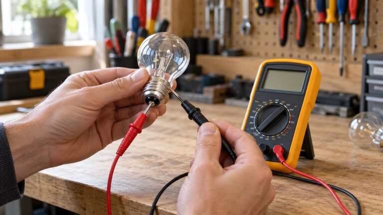
This is how to test an optocoupler with a multimeter on the bench: take the part out of its circuit, switch the circuit off, and run a diode test across the input LED pins. That check screens the LED side only. The output phototransistor needs a method the sources do not give, so this guide stops at the ratings and test conditions for that side.
Quick answer
- Only test with the part out of its circuit and the circuit switched off. The sources we opened do not describe powered checks.
- The input LED is checked with a diode test, read in both lead orders, as Fluke describes for diodes in general.
- The sources give ratings and test conditions for the output phototransistor, but no multimeter resistance or continuity step for its pins.
- Take ratings from the datasheet for your own part. The example figures here come from the Vishay 4N25 datasheet.
Electrical safety first
Work on mains circuits can kill. Before you measure anything, check that the meter’s CAT rating suits the circuit you are testing, and read the rating from the listing or the manufacturer’s manual. Panel and service work belongs to a licensed electrician.
The sources explain the danger. Portland State University’s electrical safety program says current “as low as 3 milliamperes” can cause serious injuries. The University of North Carolina Asheville’s table lists ventricular fibrillation at 1,000 to 5,000 mA and cardiac arrest with probable death at 10,000 mA and above.
CAT ratings describe the measurement environment a meter is built for, and the rating of the whole setup counts. Fluke’s user manual for its 373 clamp meter says the CAT and voltage rating of any combination of probe, accessory and meter is the lowest rating of any single component. Fluke’s safety guide advises choosing a tool rated for the highest category you could potentially use it in, and says the ratings are usually located near the input jacks. The same guide says CAT-rated meters are designed to minimize or reduce the possibility of an arc flash occurring inside the meter. The tester.co.uk guide places CAT II at mains sockets and household appliances, CAT III at fixed wiring such as switches and socket outlets, and CAT IV at the top of the scale.
Panel and service work is a separate matter. An AJC home column says that parts of a residential electrical system will require “a licensed electrician or the power company to repair.” The City of Edmonton’s homeowner permit form says that homeowners who are not certified master electricians may not install or relocate the main electrical service panel. OSHA’s electrical safety rules cover work by qualified persons, who are trained to avoid the hazards of working on or near exposed energized parts.
This guide covers one low-voltage bench check, with the part removed and the circuit off. It does not cover live circuits, panels, outlets or service wiring. Fluke’s diode test instructions say all power to the circuit must be off, and that charged capacitors need to be discharged first. OSHA’s rule says live parts “shall be deenergized before the employee works on or near them.” Portland State’s page adds that OSHA and NFPA 70E require energized parts to be de-energized and locked out before any electrical procedure.
What the 4N25 datasheet gives
The example figures in this guide come from the Vishay 4N25 datasheet, the only optocoupler datasheet we opened. Use the datasheet for your own part. The datasheet says each device consists of a gallium arsenide infrared LED and a silicon NPN phototransistor.
In the datasheet drawing, pin 1 is the anode, pin 2 is the cathode, pin 3 is not connected, and pins 4, 5 and 6 are the emitter, collector and base. Confirm the pinout for your part before you probe it.
| Item (4N25 datasheet) | Value | Condition |
|---|---|---|
| Input reverse voltage, VR | 6 V | Absolute maximum |
| Input forward current, IF | 60 mA | Absolute maximum |
| Input forward voltage, VF | 1.36 V typical, 1.5 V maximum | IF = 50 mA |
| Collector-emitter breakdown voltage, VCEO | 70 V | Absolute maximum |
| Collector-emitter breakdown voltage, BVCEO | 30 V minimum | IC = 1.0 mA |
| Collector current, IC | 50 mA | Absolute maximum |
| Dark current, ICEO | 5 nA typical, 50 nA maximum | VCE = 10 V, base open |
| Saturation voltage, VCE(sat) | 0.5 V maximum | ICE = 2.0 mA, IF = 50 mA |
The datasheet header is marked “Not for New Designs,” so check the current datasheet before you use these figures for a new design. The absolute maximum section adds that stresses above those ratings “can cause permanent damage to the device.”
Step 1: Test the input LED in diode mode
The input LED is a diode. Vishay’s measurement note also refers to the input as “the diode” in its reverse-voltage test. Fluke calls diode test mode “almost always the best approach” for a digital multimeter, and says resistance mode is typically used only when the meter has no diode setting.
Follow these steps with the part out of circuit and the power off:
- Confirm the circuit is off and that no voltage remains at the pins.
- Turn the dial to Diode Test mode. Fluke notes that this mode may share a space on the dial with another function.
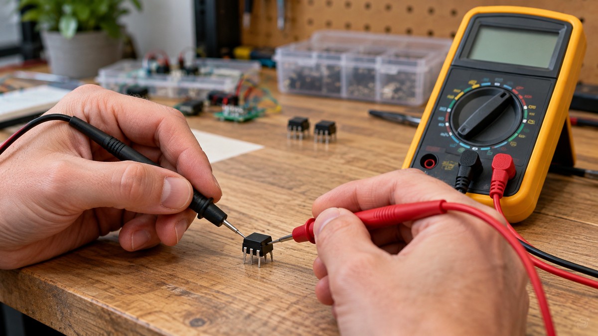
- Touch the red lead to pin 1 (anode) and the black lead to pin 2 (cathode). Fluke says a diode is forward-biased when the red lead is on the anode and the black lead is on the cathode.
- Record the reading on the display.
- Reverse the leads and record the second reading.
Fluke also says that in some cases one end of a diode may need to be removed from the circuit before it can be tested.
Step 2: Read the forward and reverse results
Fluke gives 0.5 to 0.8 volts as the drop for a good forward-biased diode among the most commonly used silicon diodes, and 0.2 to 0.3 volts for germanium. The article gives no range for LEDs, and it does not state the test voltage or test current the meter applies. The datasheet gives 1.36 volts typical at 50 mA for the 4N25 LED. Because the meter’s test current is not stated, its reading cannot be checked against that 50 mA condition. Vishay’s notes describe its reverse-voltage test as a constant current applied to the diode, read on a voltmeter of extremely high input impedance, which is a different setup from a handheld diode test.
- A forward reading in one lead order and OL in the other matches Fluke’s description of a good diode, which displays OL when reverse-biased.
- OL in both directions points to an open diode, according to Fluke.
- A reading of about 0.4 V in both directions points to a shorted diode, according to Fluke.
Fluke recommends comparing resistance readings against a known good diode. The sources we opened do not say whether that comparison is needed in diode mode, so this guide does not make the claim.
If the meter has no diode mode, Fluke’s resistance method is the fallback. Fluke gives 1,000 ohms to 10 megohms as the forward-biased resistance range for a good diode, and says a good diode reads OL in reverse. Its notes add that resistance mode does not always indicate whether a diode is good or bad, but it can confirm a fault after a diode test has already flagged one. That range is Fluke’s figure for diodes in general, and the sources we opened do not give it for an optocoupler LED.
The output side: ratings and conditions only
The 4N25 output is a silicon NPN phototransistor with a base connection. The datasheet gives a collector-emitter breakdown minimum of 30 V at 1.0 mA, an absolute maximum collector-emitter voltage of 70 V, and a dark current maximum of 50 nA at 10 V with the base open. Vishay’s measurement note says the dark current “must be measured in complete darkness,” and that ordinary daylight “might cause wrong measurement results.”
The datasheet’s saturation voltage, 0.5 volts maximum at 2.0 mA, is specified with 50 mA of forward current through the LED. That test drives the input, which is outside a bench check with the circuit off, so this guide does not describe it. Vishay’s notes show the output circuits with a supply connected, and this guide does not reproduce them.
Vishay’s application note defines the current transfer ratio (CTR) as the ratio of the output current (ICE) to the forward current (IF). The datasheet plots normalized CTR against forward current and against ambient temperature, so a CTR figure depends on its test conditions. The sources we opened give no multimeter method for CTR.
For the continuity side of meter checks in general, see how to use a continuity tester. Readers who want the transistor side of a meter check can read the NPN transistor test page.
Common mistakes
- Testing with the part still in circuit. Fluke says a resistance reading on a diode in circuit “can produce a false reading.”
- Reading one lead order only. Fluke’s method has you reverse the leads and record a second reading.
- Using the silicon range as the LED range. Fluke’s 0.5 to 0.8 volt figure is for common silicon diodes.
- Judging the whole part from the LED side. A good forward reading says nothing in these sources about the phototransistor.
- Exceeding the absolute maximum ratings, such as 6 V reverse or 60 mA forward on the input.
- Using 4N25 figures for another part. Ratings belong to the datasheet of the part you hold.
How we chose
We wanted sources a reader can open and check. The steps come from Fluke’s diode test article, and the figures come from the Vishay 4N25 datasheet. Safety statements come from OSHA’s electrical rules, a Fluke clamp meter manual, Fluke’s safety guide, a CAT explainer from tester.co.uk, two university pages, a home column in a metropolitan newspaper and a city permit form. We opened each page with curl on 2026-10-22, saved the body, and checked every quoted sentence against the fetched text. Pages that returned 403 or 404 were dropped. Searches for optocoupler bench tests mostly returned forum threads and tutorial sites, and this guide does not use them as evidence.
What we could not verify
The sources we opened do not cover the items below, so this guide leaves them out.
- A multimeter resistance or continuity reading for the output pins. The pages we opened do not give one.
- A diode-mode reading range for an optocoupler LED. Fluke’s ranges cover silicon and germanium diodes only.
- The test voltage and test current a handheld meter applies in diode mode.
- A CAT rating or voltage rating for any meter model. This guide opened no meter listing or meter manual.
- Ratings for optocouplers other than the 4N25 family.
- A replacement for the 4N25. The datasheet carries an “Alternative Device” label, and this guide did not identify the device it refers to.
Frequently asked questions
Can I test an optocoupler with the power on?
No, not with this method. Every step here assumes the part is out of its circuit and the circuit is off. Powered checks are outside this guide.
Does a forward reading prove the optocoupler works?
No. A forward reading with OL in reverse shows only that the input LED passes this screen. Nothing in the sources gives a diode-mode check for the output side.
What forward reading should the LED show on a meter?
The sources do not give a meter reading for an optocoupler LED. The forward figures in this guide are datasheet values at a set current, not meter readings.
How do I check the output transistor with a multimeter?
The sources we opened give no multimeter step for the output pins. The datasheet’s tests need forward current through the LED or a dark setup, so this guide does not describe them.
Why take the part out of the circuit before testing?
Fluke says a resistance reading taken on a diode in circuit can be false, and it describes its resistance check after the diode has been removed. Diode mode also needs the circuit off, per Fluke’s procedure.
Where do I find the CAT rating for my meter?
Fluke’s safety guide says the ratings are usually near the input jacks. Read the rating on the meter and in its manual, and treat the lowest rating of any probe or accessory as the limit, as the Fluke clamp meter manual describes.
Bottom line
Test the input LED in diode mode with the part out of its circuit and the power off, and read a forward value with OL in reverse as a pass for the LED side only. Treat the output side as untested by the sources in this guide.
Sources
- Fluke, “How to Test Diodes with a Digital Multimeter”: https://www.fluke.com/en-us/learn/blog/digital-multimeters/how-to-test-diodes (opened 2026-10-22)
- Fluke, “Guide to digital multimeter safety”: https://www.fluke.com/en-us/learn/blog/safety/multimeter-guide (opened 2026-10-22)
- Fluke 373 Users Manual, PN 3612805: https://media.fluke.com/eb9fa4dd-42de-4e9e-ad1e-b10800c1a22a_original%20file.pdf (opened 2026-10-22)
- Vishay, Measurement Techniques, Document 80061 Rev. 1.3: https://www.vishay.com/docs/80061/80061.pdf (opened 2026-10-22)
- Vishay, 4N25-X to 4N28-X datasheet, Document 81864 Rev. 1.3: https://www.vishay.com/docs/81864/4n25x000.pdf (opened 2026-10-22)
- Vishay, Application Note 04, Impact of the Current Transfer Ratio on Switching Times in Optocouplers With Transistor Output: https://www.vishay.com/docs/80579/an04_impactcurrenttransferratiooptocouplers.pdf (opened 2026-10-22)
- OSHA, 29 CFR 1910.333: https://www.osha.gov/laws-regs/regulations/standardnumber/1910/1910.333 (opened 2026-10-22)
- OSHA, 29 CFR 1910.331: https://www.osha.gov/laws-regs/regulations/standardnumber/1910/1910.331 (opened 2026-10-22)
- Portland State University, Electrical Safety Program: https://www.pdx.edu/environmental-health-safety/electrical-safety (opened 2026-10-22)
- University of North Carolina Asheville, Electrical Safety: https://www.unca.edu/ehs/electrical-safety/ (opened 2026-10-22)
- tester.co.uk, Explaining the CAT measurement categories: https://www.tester.co.uk/advice/explaining-the-cat-measurement-categories (opened 2026-10-22)
- AJC, home electrical safety column: https://ajc.com/lifestyles/home–garden/ask-the-inspector-home-electrical-safety/RmnJhSXbJpr2Be8h8JtgSJ (opened 2026-10-22)
- City of Edmonton, electrical permit application for homeowners: https://edmonton.ca/sites/default/files/public-files/assets/electrical_permit_application_for_homeowners.pdf (opened 2026-10-22)