What Is Resistance Tolerance
As an Amazon Associate we earn from qualifying purchases.
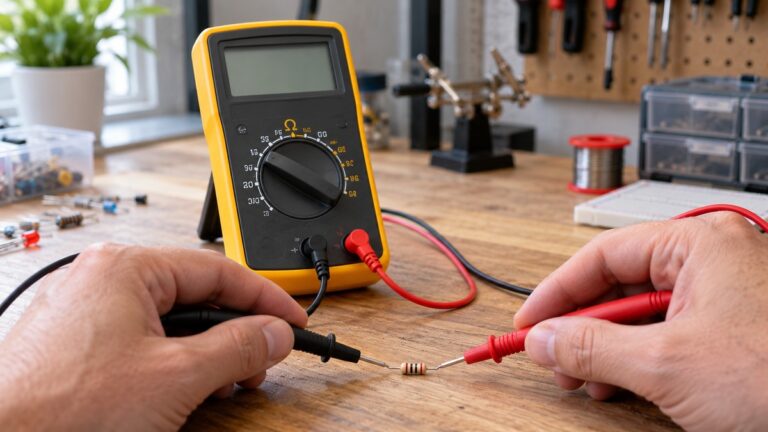
What is resistance tolerance? It is the largest allowed difference between a resistor’s marked value and its actual value, written as a percentage of that marked value. Tolerance belongs to the part and is set when it is made. A multimeter reading is a different thing, and it says something about the part only when the part is out of its circuit. This guide covers how the band is printed or coded, how tolerance differs from meter accuracy, and why a reading inside or outside the band depends on conditions.
Electrical safety
Work on mains circuits can kill. The scope here is a loose resistor on a bench, or a part lifted out of low-voltage electronics with the power off. Before you measure anything, confirm that the CAT rating printed on the meter fits the circuit you are testing; the listing or manufacturer’s manual gives that rating. This post names no meter, so it gives no CAT rating. Work on a panel or on service wiring is the job of a licensed electrician.
The Electrical Safety Foundation International (ESFI) workbook calls safety the foremost concern for anyone working on or around electricity. It recommends a qualified, licensed electrician for electrical work at home, and it ties permits and inspection to protection against electrocution and electrical fires.
Fluke’s IEC category guide warns that test equipment without a suitable category rating for the task can explode if it is used improperly. Fluke’s multimeter guide ties the choice to the most demanding location where you might test, and it wants the voltage rating to match or exceed that location.
Quick answer
- Resistance tolerance is the allowed deviation of a resistor’s real value from its marked value, given in percent.
- The FDA guide says typical resistor tolerances run from about 0.1 percent to 20 percent.
- On a four-band resistor the fourth band carries the tolerance, and a blank band means 20 percent according to Kuphaldt’s reference.
- Meter accuracy is the meter’s own error, a separate number from the part’s tolerance.
- A reading only compares with the tolerance window when the resistor is out of its circuit and the power is off.
What tolerance means
A resistor is made to a nominal, or marked, value. Materials and manufacturing methods vary, so the FDA guide says every resistor has a specified permissible deviation. That deviation is given in percent of the nominal value, measured under stated conditions, usually at 25 °C, and the guide calls it “tolerance.” Riedon, a resistor maker, defines tolerance as the maximum allowed deviation of the actual value from the nominal value.
The window follows from that definition. A 470 Ω resistor with ±5 percent tolerance may measure anywhere from 446.5 Ω to 493.5 Ω. Those limits are our own arithmetic.
Tolerance grades depend on construction. The FDA guide says composition resistors are typically available from ±5% to ±20%, and film types can be bought with tolerances down to ±0.1%. Vishay’s RWST wirewound datasheet lists a standard resistance tolerance of ±5 percent, and it gives its values as E12 and E24 preferred series values. Kuphaldt’s reference explains that the IEC defined those preferred values so that they space out evenly on a logarithmic scale.
Tolerance is also not the same as stability. Riedon gives stability its own definition, a limit on how far the value may change over time and stress, so a tolerance figure alone does not describe drift.
How the tolerance band is printed or coded
A resistor shows its tolerance either as a printed percentage or as a color band. The FDA guide says resistors usually carry markings for value and tolerance, and that the color code uses four or five bands around the body.
IEC 60062 covers marking codes for resistors and capacitors, including colour coding for resistors. The preview we opened sets the basic rules. Colour code is applied as a sequence of solid bands, and the first band sits nearest the end of the resistor wherever possible. The tolerance band must be at least 1.5 times as wide as the other bands, although the standard says that design width is not meant to be measured on a real part.
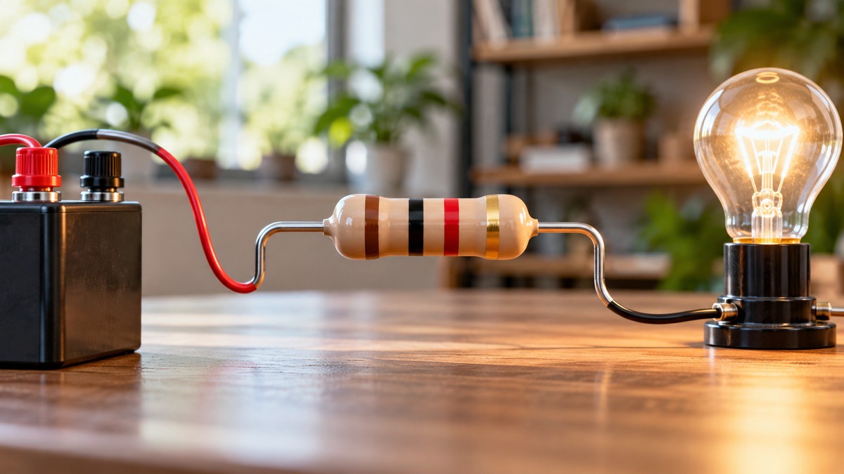
On a four-band code, the fourth band is the tolerance band. A Southern Illinois University worksheet says it gives the manufacturer’s range of tolerance for the resistance. On five-band parts the fifth band carries the tolerance, and Kuphaldt notes that brown, red, green, blue and violet are used as tolerance codes on five-band resistors only.
Kuphaldt’s examples show the mapping. A Yellow-Violet-Orange-Gold resistor reads as 47 kΩ at ±5 percent. A Green-Red-Gold-Silver resistor reads as 5.2 Ω at ±10 percent. A White-Violet-Black resistor has only three colored bands, which Kuphaldt treats as a four-band code with a blank band, meaning ±20 percent.
For the order of the bands, the FDA guide says to start from the color nearest one end of the resistor. If the colors are equally far from both ends, start from the end farther from the gold or silver band, since that band marks tolerance.
Section 5 of IEC 60062 is a letter code for tolerance on capacitance or resistance values. The preview lists that section in its contents but does not reproduce its table, so this guide gives no letter values.
Tolerance versus meter accuracy
These are two numbers for two different things. Tolerance tells you how far the part may stray from its marking. Accuracy tells you how far the meter’s display may stray from the true value of the input. A good resistor can look bad on a weak meter, so each number needs its own check.
Fluke’s knowledge base article expresses accuracy as a percentage of reading plus a number of counts, using the example ±([1% of reading] + [2 counts]). A count is one step in the least significant digit. Fluke says the percentage term matters most at the high end of a range, and that the accuracy of one particular instrument would require calibrating that unit individually.
AEMC’s technical bulletin, Understanding Uncertainty Specifications, says that digits and counts define an instrument’s resolution, but not its accuracy. For a broader look at how meters are specified, see our multimeter buying guide.
Here is the effect on a tight part. A 1 kΩ resistor marked ±1 percent has a window from 990 Ω to 1,010 Ω. With the illustrative spec above and a count of 1 Ω, a reading of 1,000 Ω spreads from 988 Ω to 1,012 Ω. That spread is wider than the window, so the reading cannot confirm the part. These figures are our own arithmetic from an illustrative spec, not the published spec of any meter.
Why a reading means something only out of circuit
A resistance reading takes in every route between the probes. Fluke’s resistance guide adds that parallel components usually lower the reading, and it advises looking at the schematic for parallel routes before trusting a value.
That is why one window can give different answers in and out of a circuit. Out of circuit, the reading reflects the part alone, so it can be compared with the window. In circuit, a parallel path can pull a good part’s reading below the window, so a reading outside the window in circuit is not proof of failure. This is our own reasoning from Fluke’s note. The note gives no figure for how much a particular board’s paths change a reading.
Fluke’s resistance steps begin by turning off power to the circuit, and they say to discharge any capacitor first. This guide assumes the same: power off for every check. For meters built around resistance measurement, see our ohm meter guide.
Worked tolerance windows
The first table is our own arithmetic. The low limit is the nominal value times one minus the tolerance written as a fraction, and the high limit is the nominal value times one plus that fraction.
| Marked value (Ω) | Tolerance | Low limit (Ω) | High limit (Ω) | Window width (Ω) |
|---|---|---|---|---|
| 1,000 | ±1% | 990 | 1,010 | 20 |
| 220 | ±10% | 198 | 242 | 44 |
| 10,000 | ±5% | 9,500 | 10,500 | 1,000 |
The second table adds meter spread from the illustrative spec ±([1% of reading] + [2 counts]). Each count is one step of the last displayed digit. These are our own assumptions, labelled as such.
| Marked part and window | Reading | Count size | Meter spread | Spread range | Verdict |
|---|---|---|---|---|---|
| 1 kΩ ±1% (990 to 1,010 Ω) | 1,000 Ω | 1 Ω | ±12 Ω | 988 to 1,012 Ω | Cannot confirm; spread is wider than the window |
| 220 Ω ±10% (198 to 242 Ω) | 220.0 Ω | 0.1 Ω | ±2.4 Ω | 217.6 to 222.4 Ω | Inside the window with margin |
The second row shows a wide window that a modest meter can confirm. The first row shows why a tight part calls for better numbers or a different approach. No page we opened sets a rule for a reading that falls partly outside its window, so that decision belongs to whoever designs the circuit.
Common mistakes
- Using the meter’s accuracy as the part’s tolerance. The two numbers answer different questions.
- Reading the bands from the wrong end. The FDA rule uses the end farther from the gold or silver band when the bands are equally close.
- Expecting a tolerance band on a three-band code. A part with three colored bands has a blank tolerance band, which Kuphaldt treats as 20 percent.
- Judging a reading taken in circuit. A parallel path usually lowers the number.
- Ignoring the spread on a tight part. A 1 percent window can be narrower than the meter’s own spread.
How we chose
We set the scope from the topic: what tolerance means, how the band is printed or coded, how tolerance differs from meter accuracy, and why an in-circuit reading can mislead. We looked for manufacturer glossaries and datasheets, the IEC 60062 standard, a government technical guide, textbook references and meter makers’ accuracy notes. We opened each page with curl on 2026-10-22, read the fetched text, and checked each quoted phrase against it. Six URLs returned HTTP 403 and were not used, so they do not appear in the sources list. Retailer listings were not used for any claim. The window tables and the meter spread are our own arithmetic.
What we could not verify
None of the pages we opened gives the letter-code values for tolerance, because the IEC preview stops before its letter table. Nothing we opened covers surface-mount markings, three-digit codes or resistor networks. No page gives drift, temperature coefficient or long-term stability figures for a named part. No page sets a pass or fail limit beyond the tolerance window, and none says how much a parallel path changes a reading on a particular board. The meter spec in our example is illustrative, not the published specification of any meter. The post does not name a meter, so it states no CAT rating. The FDA and Riedon pages describe tolerance in general terms, so the datasheet for your own part remains the final word on its grade.
Frequently asked questions
Is resistance tolerance the same as meter accuracy?
No. Tolerance is the part’s allowed deviation from its marked value. Meter accuracy is the error the instrument may add to a reading. AEMC ties digits and counts to resolution rather than accuracy, and Fluke says one instrument needs its own calibration to establish its accuracy.
What does a blank fourth band mean?
Kuphaldt’s reference treats a blank band as 20 percent. A part with only three colored bands therefore carries a ±20 percent window, which is wide enough to check the grade before relying on the value.
Which end of the resistor do I read first?
IEC 60062 says the first band sits nearest the end wherever possible. If the bands are equally close to both ends, the FDA guide says to start from the end farther from the gold or silver band. The standard’s design rule also makes the tolerance band at least 1.5 times as wide as the others.
Can I trust a reading that falls inside the window?
Only as far as the meter’s spread allows. A reading inside the window is consistent with the marking, but the meter’s percentage and counts can widen the true range around that reading. A reading close to a window edge is where the spread matters most.
Does a reading outside the window mean the resistor has failed?
No failure threshold appears in the pages we opened. A reading outside the window with the part out of circuit is a result to repeat, and the meter’s spread should be counted before calling the part bad. A reading taken with the part still wired in is not enough on its own, because a parallel path usually lowers the number.
What tolerance grades do resistors come in?
The FDA guide gives a broad range of roughly 0.1 percent to 20 percent. Vishay’s RWST datasheet lists ±5 percent for its wirewound series, and Kuphaldt’s examples run from 0.1 percent up to 20 percent. Check the datasheet or the marking for the part in front of you.
Bottom line
Read the band as the part’s allowed deviation, treat the meter’s specification as a separate error, and judge a reading only with the resistor out of its circuit and the power off.
Sources
- IEC 60062:2016, Marking codes for resistors and capacitors (preview, VDE Verlag): https://www.vde-verlag.de/iec-normen/preview-pdf/info_iec60062%7Bed6.0%7Db.pdf (opened 2026-10-22)
- Riedon, Definition of terms: https://www.Riedon.com/media/pdf-tech/DefinitionofTerms.pdf (opened 2026-10-22)
- U.S. Food and Drug Administration, Inspection technical guide: Electronic components, resistors: https://www.fda.gov/inspections-compliance-enforcement-and-criminal-investigations/inspection-technical-guides/electronic-components-resistors (opened 2026-10-22)
- Kuphaldt, Resistor color codes (LibreTexts): https://workforce.libretexts.org/Bookshelves/Electronics_Technology/Electric_Circuits_V_-_References_(Kuphaldt)/02%3A_Color_Codes/2.01%3A_Resistor_Color_Codes (opened 2026-10-22)
- Vishay, RWST wirewound resistor datasheet: https://www.vishay.com/docs/50017/rwst.pdf (opened 2026-10-22)
- Southern Illinois University, Resistor color code worksheet: https://www.engr.siu.edu/staff/spezia/Web150/website/worksheets/ResistorColorCodeWorksheet.pdf (opened 2026-10-22)
- Fluke knowledge base, Instrument accuracy of display value (KA-01125): https://my.fluke.com/en-US/article/KA-01125 (opened 2026-10-22)
- AEMC, Understanding Uncertainty Specifications for Electrical Test Equipment (technical bulletin): https://aemc.com/userfiles/files/resources/applications/multimeters/APP-UncertaintySpecs.pdf (opened 2026-10-22)
- Fluke, How to measure resistance: https://www.fluke.com/en-us/learn/blog/digital-multimeters/how-to-measure-resistance (opened 2026-10-22)
- Electrical Safety Foundation International, Electrical Safety Workbook: https://ghblp.org/wp-content/uploads/2018/09/ESFI-Electrical-Safety-Workbook-compressed.pdf (opened 2026-10-22)
- Fluke, IEC category ratings guide: https://www.fluke.com/en-us/learn/blog/safety/iec-category-ratings-use-the-right-tools-for-the-job (opened 2026-10-22)
- Fluke, Multimeter guide: https://www.fluke.com/en-us/learn/blog/safety/multimeter-guide (opened 2026-10-22)