How to Choose a Multimeter for Checking Oxygen Sensors
As an Amazon Associate we earn from qualifying purchases.
How to choose a multimeter for checking oxygen sensors comes down to three features: a DC voltage range fine enough to show a sensor swing of about 1 volt, an input resistance high enough that the meter does not pull on the signal, and an ohms range for the heater circuit. The sources we opened describe a narrow-band zirconia sensor that swings between about 0.1 V and 0.9 V when the engine runs in closed loop. This guide explains what to look for in a meter for that job, what each source says, and what the sources do not say.
Quick answer
- Pick a meter with a millivolt DC range, since the sensor swing sits between about 0.1 V and 0.9 V.
- Check the input resistance on the listing or manual, because a high-resistance source can read low.
- Use an ohms range for the heater check, and read each rating from the listing or manual before you connect the meter.
Electrical safety first
Electricity can be deadly. Fluke’s safety article says electricity is “Deadly if unleashed by improper tools.” The work in this guide is low-voltage automotive sensor work, but an oxygen sensor sits in a hot exhaust, so the safety points below come before any step.
Check that the meter’s CAT rating suits the circuit you test, and read the rating from the listing or the manufacturer’s manual. The Fluke safety article describes CAT II as covering loads such as appliances and portable tools, and CAT III as covering equipment in fixed locations. The sources we opened do not say which CAT rating an engine-bay sensor measurement needs. This guide names no meter, so it cannot quote a CAT rating for one, and the listing does not state a CAT rating for any meter named here.
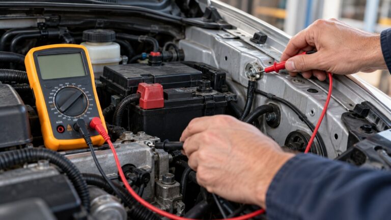
Work on a cool engine where possible. The Fluke sensor article advises routing leads clear of belts and the exhaust, and using back-probe pins or a breakout harness rather than piercing the insulation. The Fluke automotive article adds a basic rule: “Always disconnect power before resistance or continuity tests and watch for hot engine components.”
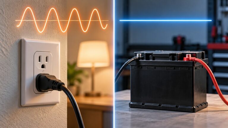
This guide gives no steps for mains outlets, panels, service wiring or any live circuit in a building. The sources we opened do not say who should do panel or service work, so this guide makes no claim about it.
What the oxygen sensor signal should look like
A narrow-band oxygen sensor produces a voltage that changes with the air-fuel mixture. The Fluke sensor article says that, with the engine at idle in closed loop, a good sensor cycles between about 0.10 V (lean) and about 0.90 V (rich), pivoting near 0.45 V (stoichiometric), several times per second. The Fluke automotive article gives the same lean and rich values, which makes two sources for the swing.
The Fluke sensor article also limits its scope. It says: “This procedure applies only to narrow-band zirconia sensors.” It adds that wide-band and titania sensors “behave differently and will not produce the 0 – 1 V swing described here.” If your sensor is a wide-band type, the 0 to 1 V check in this guide does not apply, and the sources we opened do not describe a substitute check for it.
Post-catalyst sensors may look different. The Fluke article says that post-catalyst sensors on late-model vehicles “may show a flatter trace by design,” and that this is normal and not a fault. The article treats that as normal, so a flat downstream trace is not, on that basis alone, a fault.
How we chose
The criteria in this guide come from the procedures and technical explanations in the sources we opened, not from a comparison of meters. We opened seven sources on 2026-10-21 and checked each quoted sentence against the fetched text of its page. Where a source paraphrases a rule, we paraphrase it here too.
- A millivolt DC range. The Fluke sensor article sets the meter to the mV DC range, a 600 mV range, for maximum resolution. It moves to the 6 V DC range only if the reading over-ranges or is noisy.
- Low loading on the signal. The Fluke loading article says that attaching a 10 megohm meter input to a high-resistance source can significantly change the reading.
- Ohms and continuity. The heater check in the Fluke sensor article uses a resistance measurement. The Fluke automotive article says the continuity beeper sounds when resistance is very low, typically below about 30 Ω.
- A stated safety rating. The CAT rating must be read from the listing or manual, as described in the safety section above.
Why input loading matters on a sensor line
The Fluke loading article says that the usual 1 or 10 megohm input resistance on most meters generally minimizes loading on the measured source. It names two exceptions. A low-impedance source such as a car battery is not significantly affected. A high-resistance source, such as the output of a photocell, can change reading and even the function of the device itself when a 10 megohm meter is attached. The article also warns about high-frequency AC, where the capacitance at the meter input loads the circuit more than the resistive input does.
Our own arithmetic, not a figure from the article, shows the scale. A meter input and a source form a voltage divider, so the error is roughly the source resistance divided by the sum of the source and input resistances. With a 10 megohm input and a 100 kilohm source, that error is about 1 percent. With a 1 megohm source, the same meter reads about 9 percent low. The article does not say how high the source resistance of an oxygen sensor signal is, so this guide does not put a figure on it. The listing does not state the input resistance of any meter named here, so check it on the listing or the manual before you buy.
Step by step: checking the signal
The steps below follow the Fluke sensor article. Each step is tied to that page, and none of them is a manufacturer procedure for a specific vehicle. Use the service manual for the wiring diagram and the pin locations.
- Warm up the engine. Run the engine to normal operating temperature so the engine control module (ECM) shifts into closed-loop fuel control.
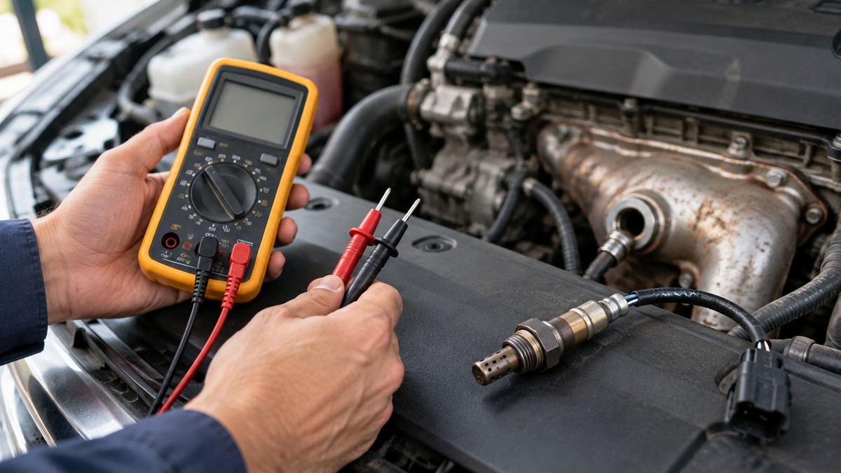
- Set the meter. Put the black lead in COM and the red lead in the V/Ω jack. Turn the rotary switch to mV DC for the 600 mV range. If the reading over-ranges or is noisy, move to V DC and press Range once for the 6 V range.
- Find the signal wire. Use the service-manual wiring diagram to identify the oxygen sensor signal conductor. Back-probe the signal pin with the red lead.
- Ground the meter correctly. Connect the black lead to the sensor-circuit ground in the same ECM connector, not to bare chassis metal.
- Watch the live voltage. With the engine at idle in closed loop, look for the cycle between about 0.10 V and 0.90 V.
- Capture the extremes. Press MIN/MAX and allow 30 to 60 seconds of runtime. The article says to check that the sensor reaches both extremes.
- Change the load. Snap the throttle or hold about 2,500 rpm briefly. The voltage should rise toward 0.9 V under enrichment and drop toward 0.1 V on deceleration. The article says a sluggish response suggests contamination or heater failure.
Heater and supply checks
If switching is slow, the Fluke sensor article suggests a heater check. With the key off, disconnect the sensor and measure the resistance between the heater terminals. The article gives a typical spec of 5 to 20 ohms. With the key on, measure the supply voltage to the heater, which the article says is usually battery voltage. The article notes that a failed heater keeps the sensor too cool to switch rapidly.
The 5 to 20 ohm figure is a typical value from one article, not a figure for any particular sensor. The sources we opened do not give a heater resistance for a named sensor, so use the sensor’s specification or the vehicle’s service information.
Reading the results
A healthy trace cycles, as described above. A signal that stays low can have causes outside the sensor. The Bosch diagnostic article describes a case where the engine control unit reported “oxygen sensor signal too low,” and the sensor “has been replaced but still outputs a low signal of 0.2 volts.” The article lists other causes, including an air leak upstream of the sensor, incorrect fuel pressure or delivery rate, sensor inputs to the ECM, and blocked injectors.
The same article warns about the codes themselves: “Lambda sensor and mixture adaptation fault codes don’t always mean the lambda sensors are faulty.” It adds that the codes can be a sign of a problem elsewhere in the engine management system.
When a multimeter trace is not enough, the Bosch article says: “In some cases it may be necessary to check the output of the lambda sensor or sensors with an oscilloscope.” It does not describe the scope procedure, so this guide does not either.
Common mistakes
- Grounding to the chassis. The Fluke sensor article warns that “Even a 100 mV ground difference will mask the entire rich-lean swing.” Use the ECM ground reference instead.
- Using the 0 to 1 V check on the wrong sensor. The procedure applies only to narrow-band zirconia sensors, as the article states.
- Working on a hot exhaust. The Fluke sensor article says to work on a cool engine where possible.
- Replacing a sensor on the code alone. The Bosch article says the codes do not always point to the sensor.
- Calling a flat downstream trace a fault. The Fluke article says it may be normal by design.
Frequently asked questions
Which range should I use to watch the signal?
The Fluke sensor article starts with the mV DC range, 600 mV, for maximum resolution. It switches to the 6 V DC range only if the reading over-ranges or causes excessive noise.
Does a 10 megohm input meter load the sensor?
The Fluke loading article says the usual 1 or 10 megohm input resistance generally minimizes loading on most sources. It does not say that this is enough for every circuit, and the sources we opened do not give the input resistance of a named sensor line.
Do I need to disconnect the sensor to check the heater?
Yes, according to the Fluke sensor article. It says to turn the key off, disconnect the sensor, and measure the heater resistance between the heater terminals.
Can I use this method on a wide-band sensor?
No, according to the Fluke sensor article. It says wide-band and titania sensors behave differently and will not produce the 0 to 1 V swing, so the check in this guide does not apply to them.
Is a low signal always a bad sensor?
The Bosch article says no. It describes a replaced sensor that still read low, and it lists air leaks, fuel pressure, sensor inputs and blocked injectors as other causes.
What does a flat downstream trace mean?
The Fluke sensor article says a flatter trace on a post-catalyst sensor may be by design and is not a fault by itself.
For a basic continuity check before the heater test, see how to use a continuity tester. For a check of the wiring feeding the sensor, see voltage drop testers.
What we could not verify
The sources we opened do not cover the following points, so this guide makes no claim about them:
- A heater resistance for any named sensor. The 5 to 20 ohm figure is a typical value from one article.
- Wide-band or AFR sensor voltages, or a method for them.
- Which CAT rating an engine-bay measurement needs.
- Who should do panel or service work, and any licensing rule for it.
- The input resistance and CAT rating of any specific meter. The listing does not state them here, because this guide names no meter.
- Oscilloscope set-up for an oxygen sensor.
The Fluke sensor article is written by a meter maker that also sells its own meters. We did not check any listing, and nothing in this guide is a product claim.
Bottom line
Choose a meter with a millivolt DC range, a high input resistance and a working ohms range, then confirm each rating on the listing or the manual before you connect it to a hot exhaust.
Sources
- https://www.fluke.com/en/learn/blog/digital-multimeters/how-to-monitor-oxygen-sensor-voltage-with-a-multimeter (opened 2026-10-21)
- https://www.fluke.com/en/learn/blog/digital-multimeters/common-automotive-testing-with-a-multimeter (opened 2026-10-21)
- https://pmmonline.co.uk/?p=42038 (opened 2026-10-21)
- https://www.boschaftermarket.com/xrm/media/images/services/news_3/2023_08_bosch_sensors_campaign/magazine_article_03_lambda_and_air_mass_sensor.pdf (opened 2026-10-21)
- https://www.fluke.com/en-us/learn/blog/safety/safe-test-tools-real-world-use (opened 2026-10-21)
- https://www.electronics-notes.com/articles/test-methods/meters/dmm-catIII-catIV-safety-ratings.php (opened 2026-10-21)
- https://www.fluke.com/en-us/learn/blog/electrical/can-you-live-with-the-burden (opened 2026-10-21)
As an Amazon Associate we earn from qualifying purchases.