Check Zener Diode
As an Amazon Associate we earn from qualifying purchases. Details
To check a zener diode you need more than a continuity beep. A zener behaves like a normal diode when forward biased, but its real job happens in reverse, at a fixed breakdown voltage that a basic diode-mode test usually never reaches. This guide walks through a two-stage check: a forward test with the meter in diode mode, then a reverse breakdown test with a small DC supply, a series resistor, and a voltmeter across the part. The circuit and the part numbers come from a university lab sheet, and the arithmetic is shown in full so you can size the resistor for your own diode before you power anything.
Quick answer
Stage one: with the diode out of its circuit, put the meter in diode mode and confirm it conducts one way and blocks the other. Stage two: reverse bias the zener from a DC supply through a series resistor, and read the voltage across the zener. A good part reads close to its rated zener voltage. A part that reads near 0 V is shorted. A part that reads the full supply voltage is open. Choose the resistor so the current stays inside the power rating on the data sheet.
What a zener diode does
Georgia State University’s HyperPhysics page describes the zener as a reverse-biased p-n junction that holds voltage close to a constant value called the zener voltage. Once enough reverse voltage is applied, the junction conducts in reverse, and small voltage changes then produce large current changes. That is why a zener is used in simple regulators and limiter circuits. The same page gives a breakdown range of about 4 volts to several hundred volts.
A Universiti Teknologi Malaysia lab sheet for the course SKEE 2742 gives a slightly different lower bound: commercial zener diodes are available from 3.3 V to several hundred volts. The two sources disagree on the low end, and the practical lesson is to read the printed marking and the data sheet of your own part rather than trust a general range. The same lab sheet states that when forward biased, a zener has the same characteristic as any other forward-biased diode. That is the reason a forward test in diode mode is still worth doing.
Specs to read before you test
The UTM pre-lab asks students to find five data sheet values for the zener they will use: the zener voltage (VZ), the test current (IZT), the impedance at that test current (ZZ at IZT), the knee current (IZK), and the maximum power (PDmax). You need the same values. VZ is what the part should read in the reverse test. IZT is the current at which VZ is specified. IZK is the minimum reverse current that keeps the part in breakdown. PDmax is the ceiling for the product of voltage and current in the part.
Stage one: forward test in diode mode
- Remove the diode from the circuit, or lift one leg. Parts in parallel can create false paths.
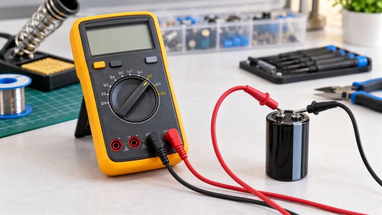
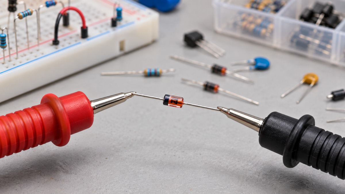
- Set the meter to diode mode. Your meter’s manual gives its open-circuit test voltage; note it, because it matters in the next step.
- Connect the red lead to the anode and the black lead to the cathode (the banded end). A working part shows a forward drop on the display.
- Swap the leads. If the part’s zener voltage is above the meter’s test voltage, the display should show an over-range indication, because the meter cannot push the part into breakdown.
- A reading near zero both ways points to a short. Over-range both ways points to an open part.
This stage cannot tell you whether the part breaks down at the right voltage. A diode-mode meter has a small open-circuit test voltage, so for most zeners it only confirms the forward junction. That is why the second stage exists.
Stage two: reverse breakdown test
The UTM circuit is the model. A DC power supply feeds a series resistor R1 of 470 ohms, then the zener (a 1N4742, listed in the lab sheet as a 12 V part) connected in reverse, with a voltmeter across the zener and an ammeter in the current path. The students step the supply through 1, 5, 10, 11, 12, 13, 14, 16, 18, 20, and 22 V and record VZ and IZ at each step. For a quick pass-fail check you need only one step, with the supply comfortably above the rated zener voltage.
- Pick a supply voltage VS above the zener voltage VZ.
- Choose a series resistor R so that the current I = (VS – VZ) / R is above IZK and below the limit set by PDmax.
- Wire the supply positive to the resistor, the resistor to the zener cathode, and the zener anode to the supply negative. This is the reverse-biased orientation.
- Set the meter to DC volts and read across the zener.
- Compare the reading with the rated VZ on the data sheet, allowing for the tolerance the data sheet states.
Worked example: sizing the resistor
For example, use the UTM values: VS = 22 V, VZ = 12 V, R = 470 ohms. The resistor drops 22 V – 12 V = 10 V, so the current is 10 V / 470 ohms = 21.3 mA. The power in the zener is 12 V x 0.0213 A = 0.255 W, which is 255 mW. Compare that with the PDmax on ythe listing data sheet before you power the circuit. The resistor itself dissipates 10 V x 0.0213 A = 0.213 W, so a quarter-watt resistor would run close to its limit.
A second example for a smaller part: a 9 V supply, a 5.1 V zener, and a 330 ohm resistor. The drop across the resistor is 9 V – 5.1 V = 3.9 V, so the current is 3.9 V / 330 ohms = 11.8 mA, and the zener power is 5.1 V x 0.0118 A = 60 mW. Both examples are arithmetic from the formula above. They are not data sheet limits for any specific part.
How to read the result
- Reading close to rated VZ: the part is breaking down where it should. Check the data sheet tolerance before you call it good.
- Reading near 0 V: the zener is shorted. With a 22 V supply and a 470 ohm resistor, a dead short would pass about 22 V / 470 ohms = 46.8 mA, set by the resistor.
- Reading equal to the supply voltage: no current flows, so the resistor drops nothing and the full supply appears across the zener. The part is open.
- Reading well below VZ with a low supply: the supply may be too low to reach breakdown. In the UTM table, the early steps at 1 V and 5 V sit below a 12 V part’s breakdown.
- Reading that drifts as you change the supply: a healthy zener holds a nearly constant voltage. The UTM sheet says the incremental resistance rZ can be as small as 5 ohms, so a 1 mA change in current moves the voltage by about 5 mV.
Common mistakes
- Testing in-circuit, where parallel parts hide a fault or invent one.
- Using no resistor. The UTM lab sheet states the circuit with a series resistor for a reason: it sets the current.
- Reversing the diode, which makes the forward drop appear instead of the breakdown voltage.
- Ignoring the meter’s own loading. A voltmeter across the zener adds a very small parallel path; the effect is negligible against milliamp currents but worth knowing.
- Skipping PDmax. Multiply VZ by the current every time.
If the zener sits in a powered board
Power the board down and prove it dead before you touch the part. OSHA’s electrical safety rule, 29 CFR 1910.333, says live parts to which an employee may be exposed must be deenergized before work on or near them, and it calls for testing circuit parts for energized conditions such as induced voltage or backfeed. Those rules cover workplaces. The same order of work applies at the bench: de-power, verify, then test. Anything connected to mains belongs to a qualified person.
Related meter guides
If you need a meter for this work, see our multimeter picks, our DC volt meter picks, and our voltmeter continuity test guide. A meter with a DC range that covers your supply and a diode mode is enough for both stages.
FAQ
Can I test a zener diode with a multimeter alone?
You can check the forward junction in diode mode. The breakdown test needs a DC supply above the zener voltage, a series resistor, and the meter on DC volts across the part.
Why does diode mode show over-range in both directions?
If the zener voltage is above the meter’s test voltage, reverse bias will not reach breakdown, so a good part blocks. Over-range in both directions can also mean an open part, which is why the second stage matters.
What resistor value should I use?
Use R = (VS – VZ) / I. With 22 V, 12 V, and 470 ohms, the current is 21.3 mA. Keep VZ times I below the data sheet PDmax.
How do I know the rated zener voltage?
Read the part marking and match it to the data sheet. The UTM lab sheet uses a 1N4742 as a 12 V part. Ranges quoted in general references differ, 3.3 V from one source and about 4 V from another.
What does a reading of 0 V across the zener mean?
It means the zener is shorted, since no voltage can build across a short. The current is then set by the resistor alone.
What does a reading equal to the supply mean?
No current flows, so the series resistor drops nothing and the full supply appears across the part. The zener is open.
Can I check a zener while it is soldered in a board?
A soldered-in reading is unreliable because parallel parts add paths. Lift one leg for a clean result, and power the board down first.
Bottom line
A zener needs two checks: a forward test in diode mode, and a reverse test that drives the part into breakdown through a resistor. Read the data sheet first, size the resistor with (VS – VZ) / R, keep the power under PDmax, and compare the reading across the part with the rated VZ. Near rated is good, near 0 V is shorted, and the full supply is open.
Sources
- Georgia State University HyperPhysics: Zener diode: source for the reverse-bias behavior and the 4 V to several hundred volt range.
- Universiti Teknologi Malaysia, SKEE 2742 Experiment 1: Zener Diode: source for the 470 ohm test circuit, the supply steps, the 3.3 V lower range, the data sheet values, and the incremental resistance.
- OSHA 29 CFR 1910.333: source for the deenergizing and test-for-energized-parts requirements.