How to Check a Guitar Pedal With a Multimeter
As an Amazon Associate we earn from qualifying purchases.
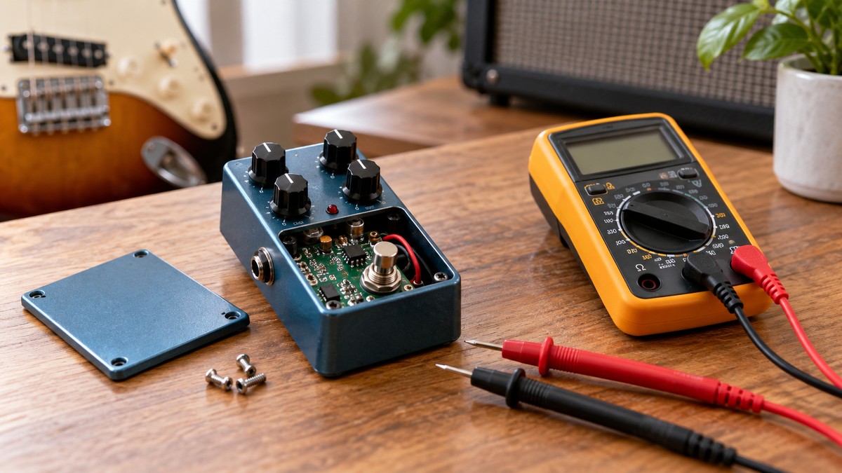
How to check a guitar pedal with a multimeter comes down to a few low-voltage bench checks: the battery or 9 V DC supply, the power jack polarity, power at the circuit board, the footswitch bypass path, and the jacks. The sources we opened cover these checks for battery-powered and 9 V DC pedals. They do not cover fault-finding inside the effect circuit itself, so this guide stops at the board.
Quick answer
- Check footswitch bypass and jack continuity with the pedal unpowered.
- A 9 V battery is nominal at 9.0 volts, and the Earthquaker guide calls a reading under 9 volts weak.
- Most pedals take center-negative power, so check each supply before you connect it.
- Keep every test on a battery or 9 V DC pedal, and stay away from mains equipment.
Electrical safety first
Work on mains circuits can kill. This guide covers only battery-powered and 9 V DC pedals. Do not open a wall adapter, and do not test a mains-powered amplifier or power supply. Before you measure anything, check that the meter’s CAT rating suits the circuit you are testing, and read the rating from the listing or the manufacturer’s manual. Panel and service work belongs to a licensed electrician.
The Fluke safety guide says to choose a tool rated for the highest category you could potentially use it in. It also says to assume every electrical component in a circuit is energized until you have positively discharged it. The University of North Carolina at Asheville safety page describes shock this way: “Electrical shock occurs when the body becomes part of the electric circuit.” It also notes that the effect may range from a slight tingle to severe burns to cardiac arrest.
How we chose
We kept only the checks that a bench meter can do on a pedal that is not running from the wall: DC voltage, continuity, and resistance on a de-energized circuit, plus a series current check when the sources describe one. The selection kept sources that state a method, a reading, or a rule, and it dropped forum claims that we could not match to a stated circuit or to a manufacturer page. Each page was opened with curl on 2026-10-21. Steps that rest only on forum posts name the forum thread in the text. No brand or model is recommended.
What you need
You need a meter with a DC voltage setting, a continuity setting that beeps, an ohms setting, and a DC current range. The Fluke continuity guide says a digital multimeter “emits a beep if a complete path (continuity) is detected.” The Fluke resistance guide says the relative mode (REL) subtracts test lead resistance, which it gives as typically 0.2 Ω to 0.5 Ω, and that the display should read 0 Ω when the leads touch.
The sources we opened do not state a required display resolution or accuracy for pedal work. They also do not name a minimum current range for a pedal’s draw.
Step 1: Check the 9 V battery
Set the meter to DC volts, then touch the red lead to the battery’s positive terminal and the black lead to the negative terminal. The Energizer EN22 datasheet lists a nominal voltage of 9.0 volts for a 9 V alkaline cell. Its discharge test runs to 4.8 volts at 21 °C, but that is a test condition for rating capacity, not a point at which the battery is dead.
The Earthquaker Devices guide gives a simple rule: if a 9 V battery reads less than 9 volts, the battery is weak, and at 9 volts or more you are set. The two sources do not agree on a cutoff, and the sources we opened do not give a replacement point.
Step 2: Check the power jack polarity
Most guitar pedals take center-negative power. A PedalPCB community thread states that standard power for guitar pedals is “center negative”, so the sleeve is positive. The Thomann listing for a Boss-compatible 9 V DC, 500 mA supply also states negative polarity inside, with a 2.1 mm inside diameter and 5.5 mm outside diameter.
Do not assume a supply is correct. In the same PedalPCB thread on 2.1 mm DC power polarity, one member checked three 9 V supplies from different makers, and all three were center positive. Check each supply before you connect a pedal.
To find the negative lug on a pedal’s power jack, use the continuity setting. Find the lug that connects to the center pin, and that lug is negative. The same thread also describes a second method: plug in the power and set the meter to DC volts to see which lug reads correctly. Use the first method with power disconnected.
Step 3: Check the power supply output and voltage
The Earthquaker Devices guide describes testing a power supply’s output at the plug. Set the meter to DC volts, insert the red lead into the terminal of the plug, and touch the black lead to the shaft of the plug. The guide says a steady reading means the supply is consistent, and that “if you get spikes or drops in your reading then something is going on with your power and it’s not safe to plug in your pedal(s).”
The same guide warns that pedals run on different voltages and that a 12, 18, or 24 V supply plugged into a 9 V pedal could “fry some components.” Check the pedal’s voltage on its label before you connect anything. This step measures only the DC plug. Do not open the adapter.
Step 4: Check power at the circuit board
If a pedal is silent or its LED stays dark, check that 9 V reaches the board. In a PedalPCB thread about a pedal that worked with no LED, a reply says “You need 9v to the switch” board, and that the ground runs through the board. A pedal that works when 9 V and ground are jumped to the LED points, but whose LED stays dark, points to a supply path rather than the LED itself.
The sources we opened do not give the voltage at each point on a specific pedal board, so compare your reading with the pedal’s schematic or the builder’s notes.
Step 5: Check for a short between supply and ground
With the power off, set the meter to continuity and check between the supply pad and the ground pad. The Earthquaker guide describes very low resistance, “less than a few Ωs”, as a connected path. The Madbean forum advice on a bypass fault lists “a short to ground” as one possible cause and recommends the continuity test on a DMM for it.
Step 6: Check the footswitch and bypass path (power off)
With the pedal unpowered, the footswitch can be checked by continuity. The Fluke guide says to test a de-energized circuit, with the component isolated from other parts. A forum post describes this method for a true-bypass pedal: set the meter to continuity, put one lead on the tip of the input jack, and the other on the tip of the output jack. The post states, “If it makes a solid beep, the pedal is bypassed.” It explains that the 3PDT footswitch connects the jacks together in bypass. If there is no solid beep, the post says the footswitch is in the effect position.
A PedalPCB reply on a 3PDT switch describes checking the center lug against the top and bottom lugs. In that reply, the effect is active when the center and top lugs have continuity, and bypassed when the center and bottom lugs do. Lug numbering differs between switch makers, so confirm the lugs on your own switch before you rely on this pattern. The Madbean thread makes the same point: continuity testing works “as long as you know which lugs are supposed to have continuity in each switch position.”
The reply that describes the center, top, and bottom pattern also states that if the LED goes out, the fault is either a short on the 3PDT board or a bad footswitch. Use that as a starting point, not a diagnosis.
Step 7: Check the input and output jacks
Jacks with a switch need a cable check. A PedalPCB thread on a switching jack reports that with no cable inserted, the switched terminal has continuity to the tip, and with a cable inserted, it has no continuity with the other terminals. That is the pattern to look for, but confirm it on the datasheet for your jack.
The same kind of check applies to a plain jack. The Earthquaker guide describes testing a cable by setting the meter to continuity and touching the tips of both plugs with the leads. A solid tone means a connection. Move the cable while you watch the meter. A tone that cuts in and out means the cable has an intermittent short. Then touch the sleeves of both plugs for the ground path.
A forum reply on bank jacks suggests finding the lug that always has continuity to the sleeve, then running straight from that lug to the same lug on the next jack. Use this only after you have confirmed the lug numbers on your jack.
Reading the results
- A solid beep means the meter found a complete path, as the Fluke guide describes.
- No beep means the meter did not find a complete path. For a switch, the sources say the position it is in decides which lugs connect.
- A resistor will not beep unless it is very low, with a forum reply giving “less than 50 – 100 ohms” as the range where a beep is likely. The sources do not give a stated threshold for pedal parts.
- A 9 V battery reading under 9 volts is weak, according to the Earthquaker guide.
- Spikes or drops in a supply reading mean the power is not stable, according to the Earthquaker guide.
The sources we opened do not give a healthy resistance for a pedal jack or switch, a current draw for any pedal, or a pass or fail figure for a supply.
Common mistakes
- Testing a live circuit for continuity. The Fluke guide tells you to test with the circuit de-energized.
- Measuring current across the circuit. A forum reply says to measure current in series, because measuring across the circuit can blow the meter’s fuse.
- Testing a part in circuit. The Fluke resistance guide says the best results come when the component is removed from the circuit, because parallel parts can change the reading.
- Trusting an unchecked power supply. A supply can be center positive, and a 12, 18, or 24 V supply can damage a 9 V pedal, per the sources above.
- Reading a beep without knowing the lugs. The Madbean thread says continuity testing works only “as long as you know which lugs are supposed to have continuity in each switch position.”
FAQ
Can I check a guitar pedal with a multimeter without power?
Yes, for continuity. The Fluke guide describes continuity testing on a de-energized circuit, and the bypass check on a footswitch is done with the pedal unpowered.
What voltage should a 9 V battery read?
The Energizer EN22 datasheet lists a nominal voltage of 9.0 volts. The Earthquaker guide says a 9 V battery reading under 9 volts is weak.
Why does polarity matter on a pedal’s power jack?
Most guitar pedals use center-negative power, and the sources warn that a wrong supply can damage components. Check the supply before you connect it.
What does a solid beep on the bypass check mean?
A forum post says a solid beep between the input and output tips means the pedal is in bypass, because the footswitch connects the jacks together.
Can a multimeter tell me if a cable is bad?
The Earthquaker guide says an intermittent tone while you move the cable points to a short. A steady tone means the cable has a connection.
Does the listing state a CAT rating for pedal work?
The sources we opened do not state a CAT rating that a pedal check needs. Read the rating from your own meter’s listing or manual.
What we could not verify
The sources we opened do not give a supply voltage limit for every pedal, a current draw figure, or a healthy resistance for each jack or switch. They do not give a pass or fail rule for a footswitch beyond the pattern a forum reply describes, and that pattern depends on lug numbering that varies by switch maker. No official manufacturer troubleshooting guide for a specific pedal was among the sources we opened. The sources do not say how to tell a loose connection from a broken part.
Related guides
Sources
- https://forum.pedalpcb.com/threads/hello-my-name-is-bifurcation-and-i-dont-know-how-to-use-a-multimeter.797/latest
- https://forum.pedalpcb.com/threads/2-1mm-dc-power-polarity.847/
- https://forum.pedalpcb.com/threads/9v-jack-long-part-positive-center-negative.2118/latest
- https://forum.pedalpcb.com/threads/prewired-led-issue.22392/latest
- https://www.madbeanpedals.com/forum/index.php?msg=37352
- https://www.fluke.com/en-us/learn/blog/digital-multimeters/how-to-test-for-continuity
- https://www.fluke.com/en-us/learn/blog/digital-multimeters/how-to-measure-resistance
- https://www.fluke.com/en-us/learn/blog/safety/multimeter-guide
- https://www.unca.edu/ehs/electrical-safety/
- https://data.energizer.com:443/pdfs/en22.pdf
- https://www.thomannmusic.com/boss_psa_230.htm
- https://forum.pedalpcb.com/threads/led-won%E2%80%99t-turn-off.3690/latest
- https://forum.pedalpcb.com/threads/switching-jack-for-muzzle-with-sidechain-passthrough.9808/
- https://forum.pedalpcb.com/threads/can-someone-please-debug-the-worlds-easiest-problem-here-for-me.15533/latest
- https://earthquakerdevices.com/blog-posts/five-ways-to-get-to-know-your-multimeter