How to Test a Car Starter Circuit with a Multimeter
As an Amazon Associate we earn from qualifying purchases.
How to test a car starter circuit with a multimeter comes down to measuring the voltage drop across the starter’s positive cable and its ground path while the engine cranks. Slow cranking or intermittent starting often points to excessive resistance in that circuit, and a voltage drop test shows which half of the circuit has the extra resistance. The Fluke guide we opened gives the method and an acceptable total drop of about 0.2 to 0.5 V. The sources we opened do not cover every vehicle, so check the figures against your vehicle’s service information.
Quick answer
- Set the meter to DC volts, using a millivolt range when you expect drops under 1 V.
- While cranking, measure from the battery positive post to the starter motor battery stud, then from the starter housing to the battery negative post.
- A total drop of about 0.2 to 0.5 V is the acceptable range in the Fluke guide. Higher readings point to corrosion, loose terminals, or damaged cables.
Electrical safety before you start
Work on mains circuits can kill. This guide covers only the 12 V starter circuit of a vehicle, which is a low-voltage DC circuit. It does not cover household outlets, panels, service wiring, or the high-voltage systems of hybrid and electric vehicles. Before you measure anything, check that the meter’s CAT rating suits the circuit you are testing, and read the rating from the listing or the manufacturer’s manual. Panel and service work belongs to a licensed electrician.
The Fluke 88 V Automotive Multimeter manual lists Measurement Category III, 1000 V, and Category IV, 600 V, for that model. Those ratings belong to that meter only. The listing does not state a CAT rating for every meter, so read the ratings for your own meter before you connect it.
The same manual says to inspect the test leads for damaged insulation or exposed metal before use, and to connect the common lead before the live lead. For in-circuit tests it says to turn circuit power off. The Fluke vehicle guide adds a safety checklist: put the vehicle in park or neutral with the parking brake on, keep hands and leads clear of moving parts, and disable the ignition or fuel so the engine cannot start during the test. The Fluke troubleshooting article also says to safely disarm the ignition before you crank the engine.
Why voltage drop, not a resistance check
A voltage drop test measures the small voltage lost across a wire, connection, or switch while current flows through it. The Fluke troubleshooting article explains that resistance-free connections would be ideal, but most of them contain at least some voltage drop. It also says that you cannot know whether a circuit is healthy until current flows through it again. The circuit therefore has to be operating when you measure. This is why the starter test is done during cranking rather than with the engine off.
The Fluke troubleshooting article gives the arithmetic behind the reading. In a DC circuit, Ohm’s law applies: V = I × R, where V is the voltage drop in volts, I is the current in amperes, and R is the resistance in ohms. The article’s example is a circuit that carries 10 amperes through 0.5 ohms, which gives a 5-volt drop. A starter circuit with a small amount of added resistance can therefore show a drop that is large enough to slow cranking, even though the wire looks sound.
The Fluke guide splits the starter circuit into two halves: the positive side from the battery post through the cable to the starter, and the ground side from the starter and engine back to the battery negative post. Testing both sides shows which half holds the extra resistance.
Preparation
Gather a digital multimeter that can read DC volts in a millivolt range, and clean access to the battery posts, the starter battery stud, and the starter housing. Probe bare metal. The Fluke guide says paint or corrosion skews results.
Set up the meter as follows. Insert the black lead into COM and the red lead into the V and ohm jack. Turn the dial to V DC. Select a millivolt DC range if you expect drops under 1 V; otherwise choose the next higher DC volts range.
If your meter has a MIN/MAX or AutoHOLD function, turn it on before you crank. The Fluke guide says MIN/MAX records the maximum reading through the whole crank event, and AutoHOLD latches the first stable reading. The Madison College automotive outline we opened lists the same Min/Max approach for measuring cranking voltage at the batteries. If your meter lacks these functions, watch the display during cranking and note the highest drop you see.
Step 1: test the positive side
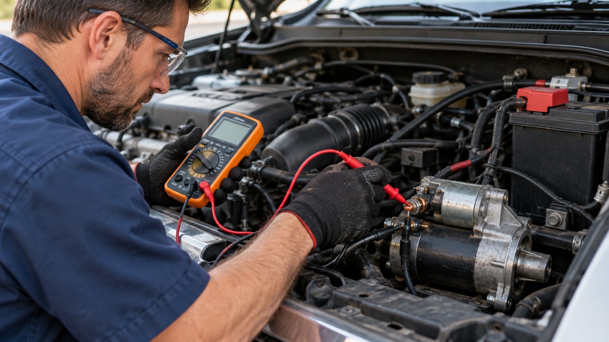
Touch the red probe to the battery’s positive post. Touch the black probe to the starter motor battery stud. This measures the voltage drop across the positive cable and its connections, as the Fluke guide describes.
Crank the engine for 4 to 5 seconds while you watch the meter. The Fluke guide says to let AutoHOLD or MIN/MAX capture the result. Record the peak drop. Release the starter and let the meter settle before you repeat the test.
Step 2: test the ground side
Keep the black probe on the starter housing or the engine block. Move the red probe to the battery negative post. Crank for a few seconds and capture the reading. The Fluke troubleshooting article describes the same kind of check: connect the meter between the engine and the negative battery terminal, then crank the engine for a few seconds while the meter records.
The Fluke troubleshooting article recommends a habit of testing grounds first. Before you test a starting, charging, or other system, it advises that you routinely test the engine and body grounds. If the drop on the engine ground is excessive, the article says to repair the engine ground circuit and retest. It also says the simplest way to stop the engine from starting during a ground test on some ignition systems without a distributor is to pull the fuel pump fuse. After the engine ground is within limits, the article says to test from the negative battery terminal to the vehicle firewall with the engine running and the major electrical accessories switched on, and to fix the body ground if the drop is too high.
The Fluke troubleshooting article also explains why the ground side matters. Many components share the engine or body as their ground, so rust, grease, vibration, or a careless repair can restrict the path back to the battery. A bad ground can affect several components at once.
Step 3: compare the readings with the limits
The Fluke starter guide gives an acceptable total drop of about 0.2 to 0.5 V, with roughly 0.3 V on the positive side and 0.2 V or less on the ground side. Use these figures as the guide states them. Some vehicle manufacturers publish their own limits, and those limits take priority over general figures.
The Fluke troubleshooting article gives separate maximum limits for use when a service manual gives no values: 0.00 V across a connection, 0.20 V across a wire or cable, 0.30 V across a switch, and 0.10 V at a ground. The article also gives a recommended working limit of 0.10 V across low-current wires and switches.
Reading the results
A reading near zero on both sides means the cranking path is losing little voltage. A reading above the acceptable total on one side points to that side of the circuit. The Fluke guide says a higher reading suggests corrosion, loose terminals, or damaged cables. Those are the causes the guide names. For a high ground-side reading, the Fluke troubleshooting article says to repair the engine ground circuit and retest. Retest after any repair and compare the new reading with the same limits. The sources we opened do not give a repair procedure for each cause beyond that.
Tips from the Fluke guide
The Fluke guide gives several practical tips. Test both sides, because the positive and ground measurements together show the full picture. Probe bare metal, as noted above. Record your findings, because the guide says voltage drop data is repeatable and useful for tracking a trend over time. The guide also says that warm or hot cables after repeated cranks may indicate internal failure, although the sources we opened do not give a temperature limit for that check.
The Fluke conclusion makes the purpose of the test clear. Voltage drop testing helps you locate excess resistance before you replace major components. When the readings are within the stated limits, the guide says you know that current reaches the starter efficiently. When they are not, the procedure leads to the fault.
The Fluke troubleshooting article gives the same order of work. If you find a restriction, repair the circuit and retest. If there is no restriction and the component still malfunctions, the article says to consider replacing the component. Practicing safe electrical service, in its words, involves measuring voltage drop before drawing conclusions.
Common mistakes
- Testing with the engine off. The voltage drop test needs current to flow, so the readings mean little until the starter is cranking.
- Probing painted or corroded metal. The Fluke guide says this skews results.
- Using a test light. The Fluke troubleshooting article says test lights are not accurate enough to diagnose electrical voltage drop and can damage most computer circuits.
- Testing only one side. The Fluke guide says positive and ground measurements together give the full picture.
- Cranking longer than needed. The Fluke guide gives a crank time of 4 to 5 seconds for each reading.
How we chose
The starter circuit voltage drop method is the one the Fluke starter guide describes step by step. The Fluke troubleshooting article and the Fluke automotive tests article both describe the same starter check, so the steps here follow those pages. We kept only the steps that a source we opened states, and we left out any step that no opened source describes. The date each source was opened is listed in the sources file for this post.
Retailer listings were not used for any procedure or safety claim. The meter ratings come from the Fluke 88 V manual, and they apply to that meter only.
What we could not verify
The sources we opened do not cover every vehicle, starter design, or wiring layout. They do not give a resting battery voltage that applies to every battery, and they do not give a temperature limit for a hot cable. They do not give a resistance or continuity check for starter solenoids that we could verify from a manufacturer page. The listing does not state a CAT rating for every meter on the market, and the sources we opened do not say what drop a specific model of starter should show.
Frequently asked questions
What does a voltage drop test show?
It shows the reduction in electrical potential as current flows through a circuit. The Fluke troubleshooting article says it occurs because of resistance in wires, connectors, and other components.
Why test during cranking?
The Fluke troubleshooting article says you must get current flowing before you can check a circuit. The Fluke guide has you crank for 4 to 5 seconds while the meter captures the reading.
What is an acceptable total drop?
The Fluke starter guide gives about 0.2 to 0.5 V in total. Your vehicle’s service information may give its own limit.
What if the positive side reads high?
The Fluke guide says a high reading suggests corrosion, loose terminals, or damaged cables on that side. Inspect the connections on that side, then retest.
Can I use any multimeter?
The Fluke guide calls for a DC volts setting, with a millivolt range when drops are under 1 V. Check your meter’s CAT rating and its DC millivolt range in its manual.
Should I check the fuse first?
A fuse check is a separate test. Read the fuse guide on this site before you start: how to check a fuse with a multimeter.
Bottom line
Measure the drop on both sides while the starter cranks, compare each side with the limits in the Fluke guide, and inspect the connections that read high before you replace parts. Stop if the work moves onto a high-voltage or airbag system.
Related guides
Sources
- https://www.fluke.com/en-us/learn/blog/digital-multimeters/how-to-check-starter-circuit-voltage-drop-with-a-multimeter
- https://www.fluke.com/en-us/learn/blog/automotive/electrical-automotive-troubleshooting
- https://www.fluke.com/en-us/learn/blog/digital-multimeters/common-automotive-testing-with-a-multimeter
- https://assets.fluke.com/manuals/88v_____umeng0000.pdf
- https://outline.madisoncollege.edu/node/17781