Trailer Circuit Testing
As an Amazon Associate we earn from qualifying purchases. Details
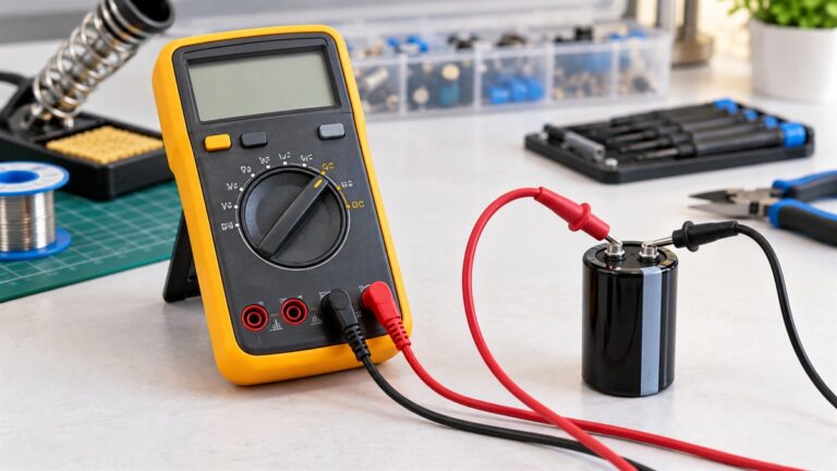
Trailer circuit testing is a short sequence of meter checks that separates three problems: no power at the tow vehicle plug, a bad ground, or a fault on the trailer harness. You need a test light or a multimeter, a helper to work the brakes and turn signals, and a pinout for your plug. This guide covers the 4-pin flat and 7-pin round connectors, tests the ground first, checks each circuit at the vehicle socket, then checks the trailer side with the connector unplugged. A worked voltage-drop example shows how to turn two voltage readings into a resistance, so a weak ground shows up as a number instead of a guess.
Quick answer
Test the ground first, because a poor ground is the most common cause of trailer wiring trouble, according to the Tow Pro Academy wiring guide. Then check each circuit at the vehicle socket with the function switched on: running lights, left turn, right turn, and (on 7-pin) brake controller output, 12 V auxiliary, and reverse. If the socket is live and the trailer is still dark, test the trailer harness with the plug disconnected. If a lamp is dim, compare the voltage at the socket with the voltage at the lamp under load.
Know your connector
Tow Pro Academy lists these functions for the two common connectors. Pin layouts and colors can vary between plugs, so confirm yours before you probe.
| Function | 4-pin flat | 7-pin round |
|---|---|---|
| Ground | White | Pin 1, white |
| Electric brake controller output | Not on this connector | Pin 2, blue |
| 12 V auxiliary power (battery charging) | Not on this connector | Pin 3, red |
| Running, tail, and marker lights | Brown | Pin 4, brown |
| Left brake and turn signal | Yellow | Pin 5, yellow |
| Right brake and turn signal | Green | Pin 6, green |
| Reverse and backup lights | Not on this connector | Pin 7, black |
What you need
- A multimeter with a DC volts range and an ohms or continuity setting, or a test light. Tow Pro Academy lists a test light or multimeter as required equipment.
- A helper to press the brake pedal and cycle the turn signals while you read the socket.
- A wire brush or sandpaper to bring a ground point to bare metal.
- Your connector pinout, from the table above or from the trailer’s documentation.
Step 1: test the ground
Tow Pro Academy says to test the ground connection with a multimeter before going further, and states that a poor ground is responsible for the vast majority of trailer wiring problems. It also says the white ground wire must make direct metal-to-metal contact with the trailer frame, and that lights on the same circuit can be grounded through their mounting hardware or back to the main ground wire.
- Unplug the trailer from the tow vehicle. Resistance readings are valid only with the circuit unpowered.
- Set the meter to ohms or continuity.
- Touch one probe to the white ground pin of the trailer connector and the other to a bare, clean spot on the trailer frame.
- A near-zero reading means the ground path is good. A high reading, or no continuity, means the ground wire, its connection, or the frame contact needs attention.
- Clean the contact point to bare metal and retest. Then check the ground at each lamp the same way.
Step 2: check the vehicle socket
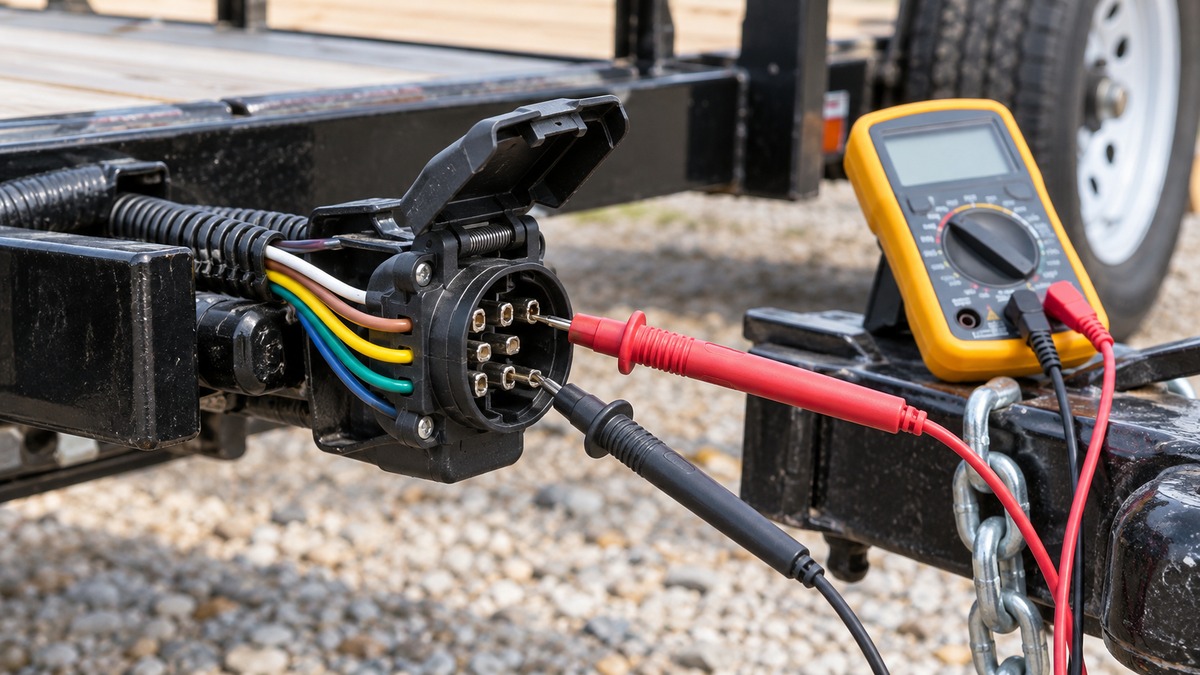
- With the trailer unplugged, set the meter to DC volts.
- Put the black probe on the socket ground pin, or on a clean bare metal point on the tow vehicle body.
- Probe the brown pin while the lights are on. You should read battery-level voltage.
- Have your helper switch on the left signal, then probe the yellow pin. The reading should pulse with the flasher.
- Repeat with the right signal on the green pin, and with the brake pedal pressed on both turn pins.
- On a 7-pin socket, check the red 12 V auxiliary pin, the black reverse pin with the vehicle in reverse, and the blue brake controller output pin while the brakes are applied.
A test light does the same job: clip it to ground and touch each pin. It tells you live or not, while a meter tells you how many volts. If a pin is dead at the socket, the fault is on the tow vehicle side. Tow Pro Academy also advises checking every circuit with the trailer plugged in before each trip.
Step 3: check the trailer side
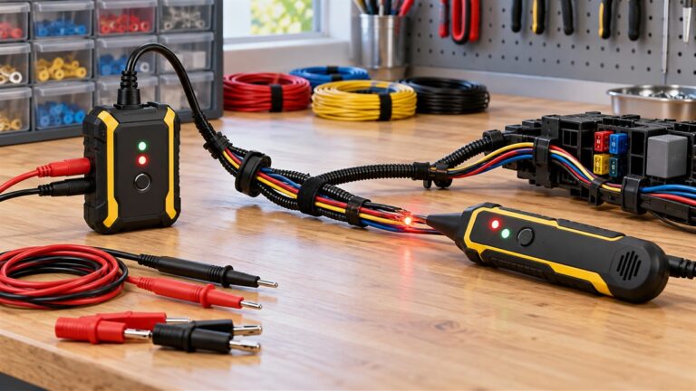
If the socket is live but the trailer lights fail, work on the trailer with the plug disconnected. Check continuity from each connector pin to its lamp: brown to the running lights, yellow to the left lamp, green to the right lamp. A pin that shows continuity to the wrong lamp points to swapped wiring. A pin with no continuity points to a broken wire or a bad splice. For a 7-pin trailer, also confirm that the blue, red, and black wires reach the brakes, the battery, and the reverse lamps they serve. A dedicated tester makes the whole check faster; see our 7-way trailer light tester picks.
Step 4: find a weak connection with voltage drop
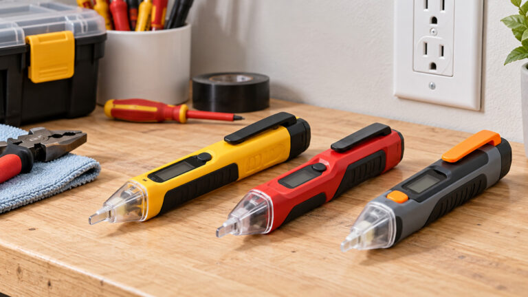
A circuit can have continuity and still starve a lamp, because the meter’s ohms setting uses a tiny current. Voltage drop under real load shows the problem. Run the circuit, then measure the voltage at the socket pin and the voltage at the lamp, both against the same ground reference. The difference is the voltage lost in the wire and its connections. Our voltage drop tester picks cover tools built for this check, and our 12V tester light picks cover the quick live-or-dead alternative.
Worked example: turn a voltage drop into resistance
For example, assume the brown circuit feeds four lamps that together draw 6 amps (an assumed figure for illustration). The socket reads 12.6 V with the lights on, and the first lamp reads 11.4 V. The loss is 12.6 V – 11.4 V = 1.2 V. The resistance in that run is 1.2 V / 6 amps = 0.2 ohms, and the check runs the other way: 6 amps x 0.2 ohms = 1.2 volts. The lamp sees 11.4 volts instead of 12.6 volts. Now take the ground side. If the lamp ground measures 0.5 V above the tow vehicle ground with the same 6 amps flowing, the ground resistance is 0.5 V / 6 amps = 0.083 ohms, or about 83 milliohms. Clean the largest loss first. Re-measure after each repair so you can see which connection mattered.
How to read the results
- Dead at the vehicle socket: the problem is on the tow vehicle: fuse, wiring, or connector.
- Live at the socket, dark at the lamp, good ground: look for a broken wire or a bad splice in that circuit.
- Dim or flickering lamps: measure voltage drop on the feed and the ground. Poor grounds are the most common cause, per Tow Pro Academy.
- Wrong lamp lights: swapped wires at the connector or the splice.
- Everything works on the bench, fails on the hitch: inspect the plug contacts and the socket for corrosion or bent pins.
Common mistakes
- Trusting wire colors without checking the pinout of your own plug.
- Testing resistance on a powered circuit, which gives meaningless numbers.
- Grounding the meter to paint or rust instead of bare metal.
- Skipping the ground test and chasing the feed wire for an hour.
- Checking only with the trailer unplugged. Tow Pro Academy advises a full plugged-in check of every circuit before each trip.
FAQ
What do I need to test trailer lights?
A test light or a multimeter, a helper to work the pedals and signals, and your connector pinout. The meter should have a DC volts range that covers at least 12 V.
Where should I start when trailer lights fail?
Start with the ground. Tow Pro Academy says a poor ground is responsible for the vast majority of trailer wiring problems and advises testing it with a multimeter before going further.
What does the blue wire do on a 7-pin plug?
It is the electric brake controller output on pin 2, according to Tow Pro Academy. The red wire on pin 3 is 12 V auxiliary power for battery charging.
Can a test light replace a multimeter?
For live or dead checks, yes. It does not give a number, so it cannot show a 1.2 V loss or a 0.2 ohm run. The worked example above needs a meter.
Why do my lights flicker with continuity everywhere?
Continuity tests use a very small current. A corroded joint can pass that and still lose volts under load, so run a voltage-drop check with the lights on.
Should I test with the trailer plugged in?
Yes, for the final check. Tow Pro Academy advises checking all circuits with the trailer plugged in before each trip. Use the unplugged tests to isolate faults.
Is the 4-pin connector missing circuits?
A 4-pin flat has ground, running lights, left turn, and right turn. It has no brake controller, auxiliary power, or reverse circuit, per the table above.
Bottom line
Ground first, then the socket, then the trailer harness, then voltage drop under load. A meter turns each of those into a number, and the arithmetic in the worked example turns two voltages into a resistance you can act on. Confirm your own plug’s pinout before you probe, and re-check every circuit with the trailer plugged in before you tow.
Sources
- Tow Pro Academy: How to Wire Trailer Lights, 4-Pin & 7-Pin Color Guide: source for the connector functions and colors, the ground-first advice, the metal-to-metal ground requirement, and the plugged-in pre-trip check.