What Is Input Impedance on a Multimeter
As an Amazon Associate we earn from qualifying purchases.
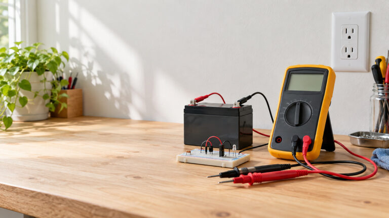
What is input impedance on a multimeter? It is the resistance the meter presents across its input terminals when it is set to a voltage range. That resistance decides how much current the meter draws from the circuit under test, so it also decides how far the act of measuring can change the voltage being read. Most digital multimeters have a high input impedance and therefore have little effect on the circuit. A few meters offer a deliberately low input impedance mode for a different job. This guide explains the concept, why it matters on high-impedance circuits, and what the manufacturers state for named meters.
Electrical safety
Mains circuits can kill. Treat any reading on a mains circuit, a distribution panel, an outlet or service wiring as work for a qualified person, and do not read this guide as a method for those circuits. Every example below is low-voltage or bench work.
East Texas A&M University’s electrical safety page warns that hazards of this kind can seriously injure or kill. The IAEI Magazine article on rescuing someone from an electric shock adds that even household currents can be deadly. Neither page is about a particular meter, so both support the general hazard only.
Before you connect any meter, check that its CAT rating covers the category of the circuit you intend to test, and take that rating from the listing or the manufacturer’s manual. Fluke’s multimeter guide advises selecting a meter whose category is at least as high as the most demanding location where you might test, and notes that the ratings are typically found near the input jacks. For the models named here, the manufacturer’s own pages state the ratings: the Fluke 113 page lists CAT IV 600V, and the Fluke 117 page describes that meter as CAT III 600 V. A rating for one model does not carry over to another.
Work on panels and service equipment should be left to a licensed electrician. The sources opened for this guide support a narrower point. The OSHA electrical work-practice rule, as reproduced by Cornell Law School’s Legal Information Institute, limits work on electric circuit parts that have not been deenergized to qualified persons. Fluke’s guide adds that a shock happens when a person’s body becomes a path in a circuit, and that any electrical work carries some risk.
Quick answer
- Input impedance is the resistance a meter presents across its input when it is set to a voltage range.
- Fluke describes most digital multimeters as above 1 MΩ, and gives about 3 kΩ for the low-impedance function on its 113 model.
- High input impedance keeps loading low. Low input impedance can drain a ghost voltage, but Fluke limits it to circuits where the extra load will not change performance.
- Check the CAT rating in the listing or manual before any mains measurement, and check each model’s own figure in its manual.
What input impedance means
Georgia Tech’s ECE lab handout on voltmeter loading describes input impedance as an internal resistance that is an intrinsic part of the voltmeter, not a resistor the student places on the breadboard. The same handout notes that the voltmeter’s input impedance is not infinite, so the reading can differ from the voltage that existed before the meter was connected. A Southern Illinois University lab on voltage measurement and meter loading describes the same mechanism more plainly: connecting a meter puts its internal resistance across the element under test.
The figure matters because manufacturers publish it. The SIU handout points to manufacturers’ specification sheets as the place where a meter’s input resistance is listed, so that is where a named meter’s value should be looked up. Fluke’s application note on dual-impedance meters gives the general picture. It says most digital multimeters sold for industrial, electrical and electronic work have high-impedance inputs above 1 megohm, so the meter has little impact on circuit performance. Older troubleshooting tools, such as analog multimeters and solenoid testers, generally sit around 10 kilohms or less. That gap explains why solenoid testers are not fooled by ghost voltages while a high-impedance meter can be.
Why input impedance matters on high-impedance circuits
Loading
Loading happens when the meter’s input becomes part of the circuit it is measuring. The SIU handout works through a voltage divider. When the meter resistance is large compared with the component it sits across, the combined resistance stays close to the component alone, and the reading stays close to the true value. As the component resistance rises, the meter’s loading effect grows and the reading moves away from the theoretical value. The handout says the effect is generally negligible when the meter’s internal resistance is large compared with the component under test.
Our own assumption, for arithmetic only: a 10 V source drives two equal 1 MΩ resistors in series, so the voltage across the lower resistor should be 5.00 V with no meter connected. A meter with a 10 MΩ input across the lower resistor reads about 4.76 V, an error of roughly 5 percent. The same circuit with a 3 kΩ input, close to the nominal figure Fluke gives for its low-impedance function, reads about 0.03 V. This is a resistive model. It ignores capacitance and the source’s own behavior, and no source in this guide states these circuit values.
Ghost voltages
A ghost voltage is a voltage that shows up on a conductor that is not connected to a source. Fluke’s application note explains that it forms when energized circuits and idle wiring share a conduit or raceway. The two conductors then act as a capacitor, and capacitive coupling carries voltage into the idle one. When a high-impedance meter is placed between that idle conductor and the neutral, the meter’s input forms a voltage divider with the coupling capacitance. The meter displays the coupled voltage, which can give a false impression of a live conductor. The note says these voltages can at times reach 80 to 85 percent of the hard voltage.
Low input impedance changes the outcome. The application note says that a low-impedance input lets the ghost voltage dissipate, so the meter shows a reading close to zero when no hard voltage is present. For the Auto-V/LoZ function on the Fluke 114, 116 and 117, the note gives a low input impedance of roughly 3 kΩ, presented as an order-of-magnitude figure. The note also says that analog multimeters and solenoid testers, which have low input impedance, are not fooled by ghost voltages, but that they should be used only where the low impedance will not disturb the circuit. A separate indicator tool with a different job is covered in how voltage testers work.
What manufacturers state for named meters
The table below lists only values that a manufacturer page or a manual copy states for a named meter. Where the model is not named, the family-level wording from Fluke’s application note is shown and labelled as such. The cell reads “not stated” where the page we opened has no number.
| Meter named in source | Input impedance as stated | Where it is stated |
|---|---|---|
| Fluke 113 | VCHEK input impedance (nominal) about 3 kΩ | Fluke product page |
| Fluke 114, 116 and 117 (Auto-V/LoZ function) | On the order of 3 kΩ, family-level wording | Fluke application note |
| Fluke 117 | Not stated; the page lists a low-impedance mode without a number | Fluke product page |
| Klein MM400 | 10 MΩ, printed as “10M” with the unit symbol lost in the copy | Manual copy hosted by the University of British Columbia |
| Keysight 34401A | 10 MΩ ±1% on the 100 V and 1000 V DC ranges; 10 MΩ or selectable above 10,000 MΩ on the 0.1 V, 1 V and 10 V DC ranges | Datasheet copy hosted at xdevs.com |
Two points stand out. The values differ from one maker to another, and they should not be averaged. Fluke’s general statement that most digital multimeters exceed 1 megohm describes a category of meters, not one model. The Keysight copy also shows that the input can be set to a much higher value on the lower DC ranges. The copy presents that as a selectable setting and does not explain when to choose it.
Low-impedance modes and their limits
Fluke’s application note recommends the regular high-impedance Vac and Vdc positions for most troubleshooting, and especially for sensitive electronic loads, on the 114, 116 and 117. It reserves the low-impedance Auto-V/LoZ position for situations where ghost voltage is suspected or where the presence of voltage is being tested.
Fluke’s 113 product page adds a warning. Low-impedance LoZ measurements put a low load on a circuit protected by an RCD, and they can trip powered GFCI and RCD circuits during phase-to-earth measurements. Read the manual’s warnings before using any low-impedance mode on an installation that has protective devices. For a related indicator tool used around high-impedance circuits, see the high-impedance test light guide.
None of the pages opened for this guide say that a low-impedance mode changes a meter’s CAT rating. The CAT rating still comes from the listing or the manual. The sources do not present a low-impedance mode as a safety feature for mains work.
How we chose
The sources were chosen for three jobs: to define the concept, to give the value a manufacturer states for a named meter, and to support the safety statements. Each page was opened with curl on 2026-10-22, and a page counted only when it returned HTTP 200 with readable text. Pages that returned HTTP 403 were not counted. That excluded Keysight’s own product page for the 34401A, OSHA’s regulation page and an electrical trade article on CAT ratings. Search results were used only to find candidate addresses, never as evidence.
Manufacturer pages and manual copies were preferred for numbers, because a figure for one model is only meaningful when the maker states it. Where a manual or datasheet came from a third-party host, the table and the source list say so. University lab handouts were used for the concept. The OSHA rule is cited through Cornell’s copy of the text, because the OSHA page itself returned 403. Retailer listings, forum posts and user-uploaded documents were not used for any claim.
Every figure in this guide comes from one of the opened sources, except the arithmetic example, which is labelled as our own assumption. The guide covers input impedance on voltage ranges only. Current ranges are outside its scope.
What we could not verify
The sources we opened do not cover the points below, and this guide does not fill them with estimates.
- A numeric low-impedance value for the Fluke 114, 116 or 117. The 117 product page lists the mode without a figure, and the application note gives only a family-level figure.
- Keysight’s own specification pages. The product page returned HTTP 403, and the datasheet was read from a copy hosted at xdevs.com. The table text in that copy is garbled during extraction, so the reading of which range carries which value should be checked against Keysight’s own PDF.
- A cleanly extracted unit for the Klein figure. The copy hosted by the University of British Columbia prints the unit symbol in a form that does not extract, so this guide reads the value as 10 MΩ. The kleintools.com manual was not opened.
- A single typical input impedance for all meters. Fluke’s general statement describes most digital multimeters, not one model.
- How large a ghost voltage must be before it changes a decision on a real installation. The sources describe the effect and give no threshold.
- Whether a low-impedance mode stays active on every model. The pages opened describe the mode but do not answer that question for every model.
- A licensed-electrician requirement. The OSHA text supports only the qualified-person point.
Frequently asked questions
Is input impedance the same as a meter’s internal resistance?
On a voltage range, the sources treat the two as one idea. The Georgia Tech handout calls input impedance an intrinsic part of the voltmeter rather than a separate component.
What value should I expect on a typical multimeter?
The sources do not give one typical figure. Fluke describes most digital multimeters as exceeding 1 megohm, and two named meters in the table state 10 MΩ for at least one voltage range. The Fluke low-impedance function sits near 3 kΩ.
Why does a meter show voltage on a wire that is not connected to anything?
Fluke attributes this to a ghost voltage, capacitively coupled from an energized conductor in the same conduit or raceway. A high-impedance meter displays it. A low-impedance function lets the coupled voltage dissipate, so the display reads near zero when no hard voltage is present.
Does a low-impedance mode make a meter safe on mains?
The sources do not support that idea. The CAT rating in the listing or manual governs the category, and Fluke warns that a low-impedance measurement can trip GFCI and RCD circuits during phase-to-earth measurement.
Why does input impedance matter for sensitive electronics?
A low input impedance draws more current from the circuit and can change how it behaves. Fluke recommends the regular high-impedance positions for sensitive electronic loads and limits low-impedance use to power circuits, or to circuits where loading will not alter performance.
Where can I find the input impedance for my own meter?
Check the specification section of the manufacturer’s manual or datasheet for the exact model. The SIU handout names specification sheets as the place where input resistance is listed. A figure from a different model, or from a general statement, does not apply to your meter.
Sources
- Fluke Corporation, “Dual Impedance Digital Multimeters” (application note): https://www.fluke.com/en-us/learn/blog/digital-multimeters/dual-impedance-digital-multimeters
- Fluke product page, Fluke 113: https://www.fluke.com/en-us/product/electrical-testing/digital-multimeters/fluke-113
- Fluke product page, Fluke 117: https://www.fluke.com/en-us/product/electrical-testing/digital-multimeters/fluke-117
- Fluke Learn, “Guide to digital multimeter safety”: https://fluke.com/en-us/learn/blog/safety/multimeter-guide
- Klein Tools MM400 manual copy, University of British Columbia: https://www.eoas.ubc.ca/courses/atsc303/Instruments/manuals/0_Klein-Tools-MultiMeter-MM400-UsersManual.pdf
- Keysight 34401A datasheet copy (document 5968-0162EN), hosted at xdevs.com: https://xdevs.com/doc/HP_Agilent_Keysight/34401A/34401A%20Multimeter%20-%20Data%20Sheet%205968-0162EN%20c20141113%20%5B6%5D.pdf
- Georgia Tech ECE 3043 lab handout, basic measurements: https://brewer.ece.gatech.edu/ece3043/NewExp2basic%20measurements.pdf
- Southern Illinois University, Lab 4A, voltage measurements and meter loading effects (Fall 2003): https://www.engr.siu.edu/staff/spezia/Web304A/Labs/LAB04A04.pdf
- East Texas A&M University, Electrical Safety: https://www.etamu.edu/electrical-safety/
- IAEI Magazine, “Safe Rescue From Electric Shock”: https://iaeimagazine.org/electrical-safety/safe-rescue-from-electric-shock/
- Cornell Legal Information Institute, 29 CFR 1910.333 (OSHA text): https://www.law.cornell.edu/cfr/text/29/1910.333