How to Choose a Multimeter for Checking Stepper Motors
As an Amazon Associate we earn from qualifying purchases.
How to choose a multimeter for checking stepper motors comes down to one job: reading the resistance of each motor winding and telling whether it is open, shorted or within its rated range. A basic digital multimeter with a low-ohms range, a zero function and an overload display covers that job. The sources we opened do not cover every stepper task, and they do not name a meter model that suits this work.
Electrical safety first
Work on mains circuits can kill. Before you measure anything, check that the meter’s CAT rating suits the circuit you are testing, and read the rating from the listing or the manufacturer’s manual. Panel and service work belongs to a licensed electrician.
The steps in this guide are low-voltage bench work on a motor that is disconnected from its driver. They do not cover live mains, outlets, panels, service wiring or any mains-fed power supply. The UK Health and Safety Executive states that normal mains voltage, 230 volts AC, can kill. The Canadian Centre for Occupational Health and Safety says electricity in homes and businesses has enough power to cause death by electrocution. A US university electrical safety fact sheet says electrical safety is about preventing electric shock and electrocution, and that work must be done by a licensed electrician.
CAT ratings describe how well a meter withstands transient energy in a given environment. Electronics Notes explains that when measuring AC lines there are often transient spikes, so the category matters as well as the voltage. FLIR describes CAT II as local-level distribution such as a standard mains socket, and CAT III as building installations including circuit-breakers, wiring and switches. Readers who want the category ratings in more depth can start with our CAT III multimeter guide. A BK Precision note gives an example of a meter marked CAT I (1000V) and CAT II (300V): it is rated for safety up to 1000 V in a category I environment, but only 300 V in a category II environment.
For a stepper motor check, the listing should state the CAT rating. If it does not, write down that the listing does not state a CAT rating, and keep the meter away from mains. A low-ohms range does not make a meter safe for household mains.
Quick answer
- Pick a meter with an ohms range that shows an overload (OL) reading when the circuit is open. The winding check and the phase-to-phase check both depend on that display.
- Choose a meter with a zero or relative function. Lead resistance adds to the reading, and the sources say zeroing reduces that error.
- Check that the listing states a CAT rating. If it does not, the listing does not state a CAT rating, and the meter should not be used on mains.
- A basic multimeter cannot check winding inductance. TechOverflow says to skip that check if you only have a multimeter. If you are unsure whether a meter or a simple circuit tester fits your task, compare them in our circuit tester versus multimeter comparison.
What the meter measures in a stepper motor
The rated current is the most critical parameter for driver setup, according to one motor datasheet guide, and it is the current that flows through each coil. Rated voltage is tied to resistance by Ohm’s law. Pololu’s Tic user guide states that the rated voltage is equal to the rated current multiplied by the coil resistance. The same guide explains that the Tic actively limits current through the motor coils, so you can safely use a power supply with a voltage above the motor’s rated voltage, as long as the current limit is set so it does not exceed the motor’s rating. That is why the voltage printed on a motor is not the voltage you should drive it at.
Current-limiting drivers change how much the coil resistance matters. The RepRap wiki says that all recent stepper controllers use a current-limiting design, so the resistance of the coils does not matter, as long as it is low enough for the current to rise fast enough. A reading still tells you whether a winding is intact. The same wiki says that if a motor’s rated amps, volts or ohms are missing from the spec sheet, the missing value can be calculated from the other two with Ohm’s law.
A forum post on selection lists coil resistance among the characteristics that steppers are selected by, along with torque, steps per revolution, step angle, NEMA frame size, polarity and shaft features. A meter helps you confirm the coil resistance value on the motor you already have, but it cannot tell you the torque.
Inductance is a different measurement. One motor guide explains that higher inductance means the coil current rises more slowly when voltage is applied. A basic ohms reading does not give you inductance.
How we chose
We limited the criteria to what the sources we opened say about winding checks. The first criterion is an ohms range with an overload display, because open windings and poor probe contact both show up as OL. The second is a zero or relative function. Melco’s resistance test says to set the meter to the ohm scale and zero it by touching the two leads together, and a forum thread reports that a bench meter’s reading can still be as much as 0.5 ohms out after zeroing. The third is a high-resistance range that can show a phase-to-phase reading of at least 5.0 MΩ, the value TechOverflow gives as the expected minimum. The fourth is a CAT rating stated on the listing.
For a broader view of meter types, see our auto-ranging multimeter guide. The criteria rest on the sources listed at the end, all opened on 2026-10-21. We did not compare meter models. The sources we opened do not name a meter that suits stepper work, so this guide does not recommend one, and no meter listing was used for a performance claim.
Preparation
Stop before you measure. Power down the system or disable the driver before you disconnect motor wires. Zbotic’s wiring guide warns that disconnecting a stepper while the driver is powered can generate a back-EMF spike that can destroy the driver chip. Disconnect the motor at its connector. Melco’s service manual gives the same step: disconnect the motor at the connectors before you measure.
Set the meter to the ohms scale and zero it by touching the two leads together. Melco’s manual says that if you do not know how to zero your meter, note the reading with the leads touching and subtract it from each measurement. Lead resistance matters at low ohms. Siliconchip’s article on resistance measurement says that test lead resistances are in series with the device under test and are included in the result, and that a four-wire technique can reduce those errors.
Have the motor datasheet ready if you can find it. TechOverflow says to compare each reading with the datasheet, or with a good motor of the same model. A forum reply lists nominal current, winding resistance and winding inductance as the key ratings to look for, but a forum reply is not a manufacturer datasheet.
Steps
Step 1: find the coil pairs on a four-wire motor
On a four-wire motor, the two wires of one coil read a low resistance between them. BuildYourCNC’s FAQ states that the wires connected to the same coil will have relatively low resistance, and that a wire from one coil to another will have no continuity. Use that rule to sort the four wires into two pairs before you measure the windings.
Step 2: identify the center taps on a six-wire motor
A six-wire motor has a center tap on each phase. Zbotic’s guide says the center tap has half the resistance to each coil end compared to the end-to-end resistance. Its example: if the end-to-end reading is 40 Ω, the center tap reads 20 Ω to each end. Measure resistance between all wire pairs, then compare each pair with that rule.
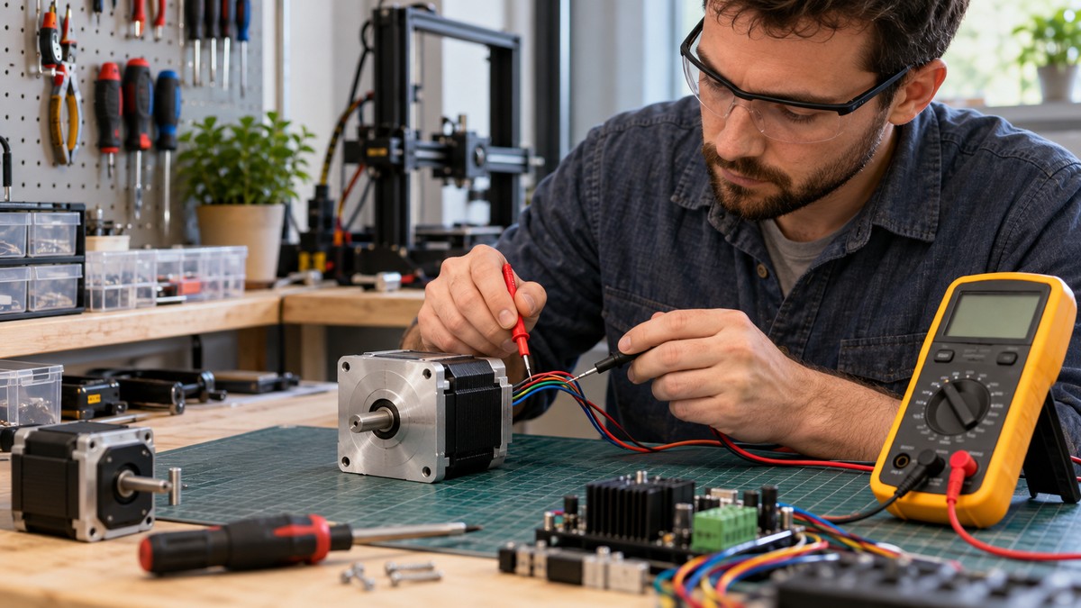
Step 3: measure each winding
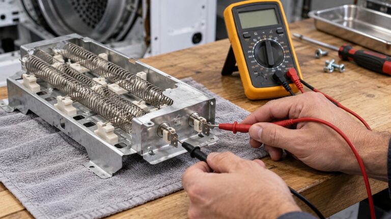
Measure the resistance of each phase winding. TechOverflow gives a general range of 0.5 Ω to 5 Ω for a phase, and notes that probe and contact resistance affect the reading. Its worked example is a motor rated at 1.5 Ω, where the author would accept 1.0 Ω to 2.0 Ω. That tolerance is one author’s rule of thumb, so compare your reading with the datasheet first.
Step 4: check phase-to-phase isolation
Measure from one pin of phase A to one pin of phase B. TechOverflow says the reading should typically be OL, and at least 5.0 MΩ. Any lower reading indicates that the phases are shorted to each other. Confirm that you have measured the correct pins before you draw that conclusion.
Reading the results
A reading that is far too low points to a shorted winding. TechOverflow gives the example of 0.2 Ω for a nominal 1.5 Ω motor. A reading that is too high points to an open winding. Melco’s manual says a low measurement indicates a shorted winding, a high measurement indicates an open winding, and in either case the motor should be replaced.
An OL reading does not always mean an open winding. TechOverflow notes that you may have measured the wrong pins, or that the probes may not touch the pin. Re-measure at several points on the pin before you decide the winding is open.
Common mistakes
- Measuring while the motor is still connected to the driver. Zbotic’s guide tells you to power down or disable the driver before disconnecting motor wires.
- Skipping the zero step. Lead resistance adds to every reading, and the forum thread reports drift even after zeroing.
- Trusting wire colour. Zbotic’s guide says some motors use different colour conventions, so verify each pair with the meter.
- Measuring the wrong pins. TechOverflow says a strange reading can come from the wrong pins, so confirm the pins before you judge the winding.
- Expecting an inductance result. TechOverflow says an LCR meter is needed for the inductance check.
What we could not verify
The sources we opened do not give a measured coil resistance for any named stepper motor, so this guide gives no target value for a specific model. They do not state a CAT rating or a resolution requirement for a multimeter used on stepper windings. The listing does not state a CAT rating for any meter, because no meter listing was opened for this post. The sources also do not describe a safe bench method for measuring current through an energized motor. Pololu’s guide says you can measure supply current with a multimeter while the motor is energized, but it does not describe the meter’s rating or protection for that task, so this guide does not give that procedure.
FAQ
Can a basic multimeter check a stepper motor?
For winding resistance, pair identification and open or short checks, the sources we opened describe ohms readings only. TechOverflow says that if you only have a multimeter, the winding inductance check should be skipped.
What resistance is normal for a stepper winding?
TechOverflow gives 0.5 Ω to 5 Ω as a general range and says the datasheet is the better reference. The sources do not give one normal value for all motors.
Why does my meter show OL on a winding?
TechOverflow lists three causes: the wrong pins, poor probe contact, or an open winding. Re-measure at several points on the pin before you conclude the winding is open.
Can I rely on wire colour to find the coils?
No, according to Zbotic’s guide, which says some motors use different colour conventions. Verify each pair with the meter.
Does coil resistance matter for a current-limited driver?
The RepRap wiki says the resistance of the coils does not matter for current-limiting controllers, as long as it is low enough for the current to rise fast enough. A reading still shows whether a winding is open or shorted.
Do I need a multimeter with a CAT rating for a motor check?
The sources we opened do not set a CAT rating for winding checks on a bench. Check the listing for any stated CAT rating, and do not use the meter on mains, outlets or panels.
Sources
- https://www.hse.gov.uk/pubns/indg231.pdf (opened 2026-10-21)
- https://www.ccohs.ca/oshanswers/safety_haz/electrical.html (opened 2026-10-21)
- https://des.umd.edu/about/occupational-safety-health/electrical-safety-fact-sheet (opened 2026-10-21)
- https://www.electronics-notes.com/articles/test-methods/meters/dmm-catIII-catIV-safety-ratings.php (opened 2026-10-21)
- https://www.bkprecision.com/knowledge/technical-notes/5/what-do-the-input-cat-ratings-mean (opened 2026-10-21)
- https://flir.com/discover/professional-tools/what-do-cat-ratings-mean (opened 2026-10-21)
- https://www.pololu.com/docs/0J71/all (opened 2026-10-21)
- https://reprap.org/wiki/Stepper_motor (opened 2026-10-21)
- https://zbotic.in/stepper-motor-datasheet-reading-understanding-phase-current-steps/ (opened 2026-10-21)
- https://melco-service.com/docs/XT_Tech_Manual/Troubleshooting/Testing_Methods/Stepper_Motor_Resistance_Test.htm (opened 2026-10-21)
- https://techoverflow.net/2021/11/16/how-to-check-a-stepper-motor-for-open-short-circuit/ (opened 2026-10-21)
- https://buildyourcnc.com/FAQ/14410 (opened 2026-10-21)
- https://zbotic.in/stepper-motor-wiring-4-wire-6-wire-8-wire-types-explained/ (opened 2026-10-21)
- https://siliconchip.com.au/Issue/PE/2023/August/Wide-Range+OhmMeter (opened 2026-10-21)
- https://www.eevblog.com/forum/testgear/how-to-zero-ohm-offset-on-brymen-bm257s/msg3386818/ (opened 2026-10-21)
- https://forum.arduino.cc/t/meaning-of-stepper-motor-specifications/440541 (opened 2026-10-21)
- https://forum.digikey.com/t/stepper-motors/32318 (opened 2026-10-21)