Circuit Tester vs Multimeter: Which One Do You Need?
As an Amazon Associate we earn from qualifying purchases. Details
Updated 19 October 2026
Author: Editorial team, bestmultimeter2020.com
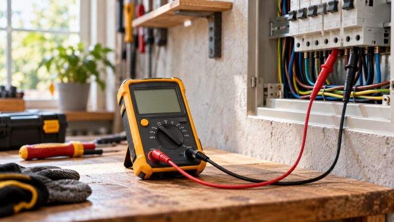
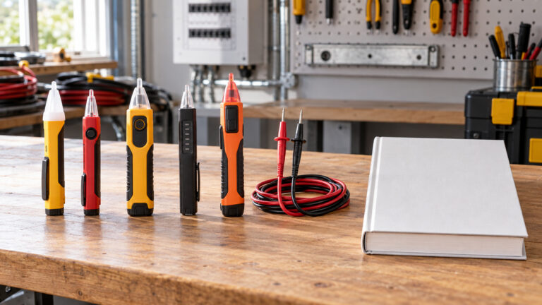
If you are weighing a circuit tester vs multimeter, the first question is what you need to know. A circuit tester is a simple handheld tool that shows whether voltage or continuity is present. A multimeter measures voltage, current and resistance and shows a number. Neither tool proves on its own that a circuit is dead, and both can mislead when used outside their design. The sources we opened do not define the term “circuit tester” in one standard way, so in this post the term means a simple handheld tester that indicates presence of voltage or continuity without a measured value.
Quick answer
- Use a circuit tester when the question is yes or no: is voltage present, or is a path continuous. Use a multimeter when you need a value, a range or several quantities.
- Neither tool confirms a circuit is dead by itself. The Fluke absence-of-voltage guide says “You must use a voltage tester to confirm it’s actually dead.”
- Input impedance decides whether a tool can show a false reading from stray voltage on nearby wiring. High-impedance inputs are the ones that can read ghost voltage, so the sources recommend low-impedance settings for those circuits.
What each tool answers
The table sets out the main questions each tool answers. The multimeter entries come from the Fluke learn pages on digital multimeters and the Fluke 87 manual. The circuit tester entries are general and are kept short, because the sources we opened do not describe circuit testers as a product category.
| Question | Circuit tester | Multimeter |
|---|---|---|
| Is voltage present? | Yes or no indication | A numeric reading on a chosen range |
| What is the value? | Not the job of a presence tester | Yes, the reading shows the value |
| Is the path continuous? | Some models include a continuity indication | Continuity mode with an audible tone |
| Current | Not the usual function | Yes, with the meter in series or with a clamp accessory |
| Input impedance | Varies by design; the sources describe solenoid testers as low impedance | High impedance on the standard voltage ranges |
The Fluke learn article on digital multimeters describes them as tools for voltage, current and resistance. The Fluke voltmeter article draws the same line from the other side: a voltmeter “only measures voltage, while a digital multimeter can measure multiple electrical quantities, including voltage, current, and resistance.” That difference is the first thing to settle. If one number is enough, a presence tool may do the job. If you need the number, or several functions, a multimeter is the better fit.
Impedance is the hidden difference
Input impedance is the resistance the tool presents to the circuit it measures. The Fluke dual impedance article puts the numbers side by side. “Older troubleshooting tools such as analog multimeters and solenoid testers generally have low impedance input circuitry around 10 kilohms or less.” Most digital multimeters for electrical work, by contrast, have “high impedance input circuits greater than 1 megohm.”
That gap matters on circuits with stray voltage, which is voltage that appears on a conductor because it runs close to an energized one. The Fluke product page for its stray voltage adapter calls this ghost voltage and ties the cause to capacitance between nearby wires. Because a high-impedance input has very little current draw, the stray voltage has nowhere to go and can show up as a reading. A lower-impedance tool presents a load that drains the stray voltage, so the reading drops.
The Fluke dual impedance article also says low-impedance tools are not affected by ghost voltages, but they should only be used on power circuits, or on circuits where the load will not change the circuit’s behavior. The article recommends a low-impedance setting on sensitive circuits and on suspect readings. That is the practical rule: a high reading on a wire that should be dead is a reason to check with a different tool, not a confirmation.
Two calculations for impedance
Take the ratio of the two impedance levels in the sources. The formula is a simple division:
Impedance ratio = high impedance divided by low impedance.
Using the sources’ own figures, a high-impedance input of 1 megohm (1,000,000 ohms) against a low-impedance input of 10 kilohms (10,000 ohms) gives 1,000,000 divided by 10,000 = 100. The high-impedance path is about 100 times higher, so it draws about one-hundredth of the current the low-impedance input draws at the same voltage.
The Fluke dual impedance article also gives a low-impedance setting figure. It says the Fluke low-impedance function “has a low input impedance on the order of three kilohms.” Against the same 1 megohm high-impedance input, 1,000,000 divided by 3,000 = 333.3. On this figure the high-impedance mode presents about 333 times more impedance than the low-impedance setting. These are our calculations from the stated figures. They are not measurements of any tool, and the sources do not give the impedance of common circuit testers.
Confirm dead before you rely on either tool
The Fluke absence-of-voltage guide is the clearest statement in the sources on this point. “You must use a voltage tester to confirm it’s actually dead.” It also warns that “Even when equipment appears to be shut down, voltage can still be present.” A circuit that has been switched off is not proof that it is de-energized, so the check comes before any work starts.
The same guide describes the live-dead-live sequence, which NFPA 70E requires for absence-of-voltage checks. The sequence checks the tester on a known live source, checks the target, then checks the tester on a known live source again. This makes sure the tester was working during the check. The Fluke multimeter safety guide makes the same point for meters: use a known voltage source or a proving unit to confirm the meter is working, and do not assume it is.
The sequence applies to a circuit tester and to a multimeter. If you cannot confirm a known source for the check, do not treat a blank display as a result. Stop, and call a licensed electrician for work on panels, service equipment or any circuit you cannot confirm as dead.
Where a multimeter adds value
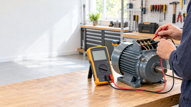
A multimeter gives you a number, which a presence tester cannot. That number matters when you need to compare a reading with a rating, a specification or a second measurement. The Fluke learn article on digital multimeters says they measure voltage, current and resistance, and it notes that digital multimeters have high input impedance, which reduces the effect of the meter on the circuit being measured.
A multimeter also covers functions a presence tester does not. Continuity mode, the diode test and resistance mode all sit on the same dial. The Fluke 87 manual describes continuity as an audible tone that tells you when a path is complete, and it lists the diode check as a separate function. Those checks are useful on a bench, but they are not a substitute for the voltage check that comes first on a live-looking circuit.
The trade-off is size and speed. A multimeter is a larger tool that needs setting up, while a presence tester is a quick first look. The sources do not compare the two on time, so we do not give a figure for that. The choice depends on whether the task needs a value or only a presence check.
Where a circuit tester is enough
The sources we opened do not give a list of jobs where a circuit tester is enough. They do make clear that presence checks come first. Fluke’s guidance is that a voltage tester confirms the circuit is dead before any further measurement, so a presence tool is the step that answers the first question. Once a value is needed, the meter takes over.
If the presence tool shows voltage and the job still calls for a value, use a multimeter with a CAT rating that fits the circuit. The CAT rating is printed near the input jacks of a meter, according to the Fluke clamp meter ruggedness article, and the probes should carry an equal or greater rating. Read those ratings before you connect any test lead.
A multimeter for the value side of the choice
The multimeter below is listed on Amazon. It stands for the value side of the choice. It is not a circuit tester, and it does not replace the voltage check described above.
1. Fluke 87V Industrial Digital Multimeter, for Advanced Troubleshooting, Measures 1000 V AC/DC, Peak (Multimeter side: CAT-rated values and high counts)
Specs from the listing (checked 2026-10-11):
- Style: INDUSTRIAL TRUE RMS MULTIMETER
- Measurement Type: Multimeter
- Warranty Description: 10 years
Pros
- The listing states CAT III 1000V and CAT IV 600V safety ratings
- Switchable resolution from 6000 to 20,000 counts for finer readings
- Peak capture on intermittents as fast as 250 µS, per the listing
Cons
- The listing shows no non-contact voltage function, so it gives numbers but does not confirm a dead circuit by itself
- At 1.3 pounds and 9.49 x 6.5 x 3.5 inches it is a bench-sized meter rather than a pocket tool
Best for: Voltage, current and resistance readings where a presence tool gives no numbers
Skip if: You need a pocket-size go or no-go check on a receptacle
View on Amazon (affiliate link)
The listing states a CAT III 1000V and CAT IV 600V safety rating, and it lists a switchable resolution from 6000 to 20,000 counts. Those two details are the ones that make the meter useful for a value check on a mains circuit, and they are the ones a presence tool cannot give. The listing does not show a non-contact voltage function, so the meter gives numbers but does not confirm a circuit is dead by itself. Use it with the check sequence above.
Ghost voltage affects both tools
The Fluke tool description says stray voltage is caused by the capacity between wires, and that a high-impedance input gives an incorrect reading because the stray voltage has nowhere to go. That applies to any high-impedance tool, including a multimeter on its standard voltage ranges. A low-impedance setting or a dedicated stray voltage adapter reduces the problem, according to the same source.
The practical lesson is to treat any unexpected voltage reading on a conductor you believe is dead as a reason to stop, not to proceed. Check with a different tool, use a low-impedance setting if the meter has one, and confirm the circuit is dead with a voltage tester. If the circuit is in a panel, a service enclosure or any equipment you cannot isolate, call a licensed electrician.
Safety notes for both tools
Panels and service equipment are out of scope for this guide. A licensed electrician should do or direct that work, whatever tool is in your hand. This applies to presence testers and to multimeters.
Check the rating before use. The Fluke safety guide advises choosing a tool rated for the highest category you could meet, which applies to a circuit tester and a multimeter alike. Read the category and voltage on the label before you connect a tool to a circuit.
Check the tool before you rely on it. The Fluke safety guide says a damaged meter or damaged test leads should never be used, and that the meter should be verified against a known source. A circuit tester needs the same checks, because a faulty tool gives a blank display that looks like a dead circuit.
For the first-use steps of a voltage tester, see how to use a voltage tester. For a continuity check on a wire or a fuse, see how do I use a continuity tester.
How we chose
We used Fluke learn pages and Fluke manuals for the functions, the impedance figures and the confirm-dead sequence, because those pages describe the tools and the procedure directly. The Fluke voltmeter article supplies the comparison of a voltmeter with a multimeter. We did not use Wikipedia, retailer pages or blogs for any safety or procedure claim. The multimeter card is built from its Amazon listing data only. The guide gives no prices and no ratings.
What we could not verify
- The sources we opened do not define “circuit tester” as a product category, and they do not list which circuit testers are low or high impedance.
- The sources do not give the impedance of common circuit testers, so this post does not compare a tester’s input with a meter’s input in absolute terms.
- The sources do not give a time comparison or a skill comparison between the two tools.
- The listing for the multimeter pick does not state a non-contact voltage function, so it does not replace a voltage tester.
FAQ
What is a circuit tester used for?
In this post, a circuit tester is a simple handheld tool that shows presence of voltage or continuity without a measured value. The sources we opened do not define the term in one standard way. Use it for a yes-or-no check, then confirm the circuit is dead with a proper voltage tester before any work.
Can a multimeter replace a circuit tester?
A multimeter can do the presence check when it is set to a voltage range, and it gives a value as well. The Fluke voltmeter article says a digital multimeter measures multiple quantities, which makes it more versatile. A multimeter does not remove the need for the check sequence on a live-looking circuit.
Why does a tester show voltage when the circuit is off?
The most likely cause, from the sources, is stray or ghost voltage caused by capacitance between nearby wires. A high-impedance input cannot drain it, so it shows as a reading. A low-impedance setting or a stray voltage adapter reduces the problem, according to the Fluke pages. Treat the reading as a reason to stop and check again.
Is a multimeter voltage reading enough to confirm a circuit is dead?
No. The Fluke absence-of-voltage guide says a voltage tester is what confirms equipment is dead. A reading of zero on a multimeter is useful only after the meter has been checked on a known source before and after the measurement.
Which should I buy first?
Buy the tool that answers your first question. For a presence check on outlets, lights and cords, a circuit tester or voltage tester is the first step. For values, resistance, continuity and diodes, a multimeter is the better first buy. Check the CAT rating on either tool before it touches a circuit.
Bottom line
Use a circuit tester for the yes-or-no check and a multimeter when you need a value. Confirm a circuit is dead with a voltage tester, check the tool on a known source, and read the impedance behavior before you trust a reading. Panels and service equipment go to a licensed electrician.
Sources
- Fluke learn: About absence of voltage testing: the voltage tester confirmation rule, the shutdown warning and the live-dead-live sequence
- Fluke learn: Dual impedance digital multimeters: the low and high impedance figures, ghost voltages and the low-impedance setting
- Fluke learn: What is a digital multimeter?: the measurement functions and the high input impedance of digital multimeters
- Fluke learn: Guide to digital multimeter safety: the highest category rule, the known source check and the damaged meter advice
- Fluke learn: What is a voltmeter, and how does it compare with a multimeter?: the difference between a voltmeter and a digital multimeter
- Fluke TL225 stray voltage adapter product page: the ghost voltage cause and the lower-impedance solution