How to Test a Solder Joint With a Multimeter
As an Amazon Associate we earn from qualifying purchases.
How to test a solder joint with a multimeter comes down to one narrow question: with the board de-energized, does the meter show a low-resistance path through the joint? A continuity check can show that a joint conducts. It cannot show that the joint is mechanically sound, or that its resistance is low enough for the circuit to work reliably. The sections below cover the continuity method, what a beep does and does not mean, and where the sources we opened stop.
Quick answer
- Use continuity mode with the board de-energized. Fluke’s continuity guide says to “Turn the dial to Continuity Test mode.”
- A beep marks a low-resistance path. Fluke’s automotive guide places it at about 25 to 50 ohms, while Fluke’s continuity guide ties the beep threshold to the range setting.
- A beep does not prove the joint is sound. The Adafruit guide warns that a cold connection “will appear connected,” and the sources we opened give no pass limit for a joint.
Electrical safety
Work on mains circuits can kill. Before you measure anything, check that the meter’s CAT rating suits the circuit you are testing, and read the rating from the listing or the manufacturer’s manual. Panel and service work belongs to a licensed electrician.
This guide covers one low-voltage case only: a board or assembly with its power removed, tested on a bench. It does not cover a powered board, an outlet, a panel or service wiring. This guide names no meter, so the listing does not state a CAT rating for any meter discussed here. Do not use these methods on anything connected to mains.
Fluke’s continuity guide says to test with the circuit de-energized, and Fluke’s resistance guide lists “Turn Off Power to Circuit” as its first step. OSHA’s electrical standard, 29 CFR 1910.333, is written for qualified workers in industrial settings. It says that parts which have been deenergized but not locked out or tagged shall be treated as energized parts. Our own assumption is that a bench board deserves the same caution: confirm the power is off before any probe touches it.
What a continuity beep tells you
In continuity mode, a meter beeps when it finds a low-resistance path. Fluke’s automotive guide says a beep indicates continuity, typically at resistance below about 25 to 50 ohms. Fluke’s continuity guide gives a different example: on a 400.0 Ω range, a meter typically beeps if the component has 40 Ω or less resistance. The threshold depends on the model and the range, so a beep alone does not give a resistance value.
The Adafruit continuity guide warns about a joint that looks fine. A cold solder connection “will appear connected” but is not. That is why a beep is a weak test of joint quality. The Cal Poly paper describes monitoring resistance increase in a solder joint as a common non-destructive test method. Its abstract also says no research has yet established a relationship between crack area and resistance change. A rising resistance reading is therefore a signal to investigate, not a measure of crack size.
What you need
- A digital multimeter with a continuity mode and an ohms (Ω) setting. Fluke’s continuity guide says the continuity mode is often combined with resistance, and that some models need a separate continuity button press.
- Test leads in the jacks the meter’s manual specifies. Fluke’s continuity guide says to insert the black lead into COM and the red lead into the VΩ jack, and to remove the leads in reverse order afterwards: red first, then black.
- A board with its power removed, and any capacitors discharged. Fluke’s automotive guide says to verify that capacitors are fully discharged before testing continuity.
- A reference for which joint is being tested. Stanford’s lab handout says students are shown examples of good and not-so-good solder joints to inspect, but the handout does not describe an inspection method.
Steps
Step 1: Confirm the board is de-energized
Remove power from the board before any probe touches it. Fluke’s resistance guide lists “Turn Off Power to Circuit” as its first step, and Fluke’s continuity guide tests components with the circuit de-energized. The sources we opened do not describe how to confirm that a board is de-energized, so this step relies on the rule itself and not on a sourced procedure.
Step 2: Isolate the joint from the rest of the circuit
Fluke’s continuity guide says to connect the test leads across the component being tested, and to “ensure the component is isolated from other components in the circuit.” Our own inference is that a parallel path through other parts could make an open joint read as connected. The guide does not describe this effect directly, so treat the explanation as an inference.
Step 3: Set continuity mode
Fluke’s continuity guide says to “Turn the dial to Continuity Test mode.” Some models also need a continuity button press. With the probes separated, the display may show OL and Ω, which is a normal open reading and not a fault by itself.
Step 4: Make firm probe contact
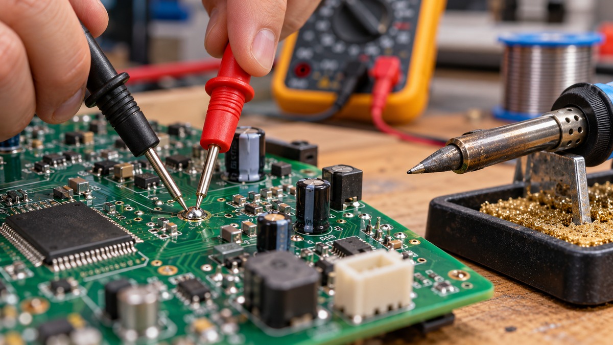
The Stanford handout says “Multimeter probes have to make firm contact with the circuit to work reliably.” Poor contact, it says, adds an extra resistance at the point of contact, which creates an error in the measurement. Place each probe on the solder and on the pad or lead it joins, and keep the probe still while the reading settles. The handout does not give a settling time, so the sources we opened do not say how long to wait.
Step 5: Check the leads and use the lowest range for connections
Fluke’s resistance guide says the relative mode “automatically subtracts test lead resistance.” It also says that, ideally, if the test leads touch, the display should show 0 Ω. Touch the leads together first and note the reading, so you know what the leads add. Fluke’s continuity guide advises using the lowest range setting for components that should have a low resistance, such as electrical connections or switch contacts.
Step 6: Read the beep and the display
Fluke’s continuity guide says the meter beeps when a complete path is detected, and does not beep when the circuit is open. Fluke’s automotive guide places the beep at roughly 25 to 50 ohms. Read the display as well as the beep, because a beep alone does not give a value. The sources we opened do not give a resistance limit that separates a good joint from a bad one on any board.
Reading the results
- A beep with a low reading means the meter found a low-resistance path through the joint. It does not prove the joint is sound, because a cold connection can also appear connected, as the Adafruit guide warns.
- No beep, or an open display, means the meter did not find a complete path. Fluke’s continuity guide says the meter will not beep when the circuit is open. The guide does not list the next steps after that.
- A reading that rises over time is what the Cal Poly abstract calls a monitored resistance increase, a common non-destructive test method. The abstract gives no threshold for a failing joint.
Common mistakes
- Testing a powered board. Fluke’s guides say to test with the circuit de-energized and to turn off power first.
- Trusting a single beep. The Adafruit guide shows that a cold joint can appear connected, so one beep is not a pass.
- Poor probe contact. The Stanford handout says it adds error at the point of contact.
- Leaving other parts connected to the joint. Fluke’s guide says to isolate the component before testing.
For board-level continuity checks, see the PCB board testing guide. For the basic continuity mode on a meter, see How Do I Use a Continuity Tester. For a wider look at continuity testers, see the circuit tester roundup.
How we chose
We chose sources a reader can open and check: manufacturer guides from Fluke, an electronics learning guide from Adafruit, a university lab handout from Stanford, an academic repository abstract from Cal Poly, and the OSHA electrical standard in the Code of Federal Regulations. We opened each page with curl on 2026-10-22 and matched each quoted phrase against the fetched text. Search snippets were not used as evidence. Two pages were excluded because they did not open: the NIOSH PDF returned 403 and a Santa Clara University blog post returned 410. Retailer listings were not used, because this topic needs procedure and not product data. Most of the sources cover continuity testing in general, not solder joints in particular, and we say so where it matters.
What we could not verify
The sources we opened do not cover the following points, and this guide does not fill those gaps with claims:
- A resistance value that separates a good solder joint from a bad one on any board.
- How a meter reading relates to joint quality or to the joint’s lifetime. The Cal Poly abstract says no research has yet established the crack-area link.
- Any acceptance criteria for solder joints. We did not open a published industry standard or a manufacturer acceptance limit.
- The CAT rating or other ratings of any specific meter. The listing does not state a CAT rating for any meter, because this guide names none.
- How to confirm that a board is de-energized before testing. The sources we opened describe the rule, not a verification method.
- Whether a given meter’s continuity threshold applies to the joint under test. The Fluke pages give thresholds for their examples, not for every model.
FAQ
Can a multimeter prove that a solder joint is good?
No. A continuity beep shows a low-resistance path. The Adafruit guide warns that a cold solder connection “will appear connected” when it is not, so a beep does not prove joint quality.
Which mode should I select?
Fluke’s continuity guide says to turn the dial to Continuity Test mode. Some models also need a continuity button press, and the mode is often combined with resistance (Ω).
Why does lead resistance matter?
Fluke’s resistance guide says the relative mode subtracts test lead resistance. That matters most for very low readings, where the leads can add a noticeable share of the total.
Can I test a joint with the board powered?
The sources we opened say to de-energize the circuit before a continuity or resistance test. This guide does not cover powered boards.
What does an open circuit look like on the meter?
The meter stays silent. Fluke’s continuity guide says the DMM will not beep when the circuit is open, so no beep means no complete path was found.
Does a rising resistance reading prove a crack?
The Cal Poly abstract says monitoring resistance increase is a common non-destructive method, and that no research has yet established the link between crack area and resistance change. The abstract does not treat a rising reading as proof of a crack.
Bottom line
Use continuity mode on a de-energized board to check that a joint conducts. Treat a beep as a continuity result only, and not as proof that the joint is sound.
Sources
- https://www.fluke.com/en/learn/blog/digital-multimeters/how-to-test-for-continuity
- https://www.fluke.com/en-us/learn/blog/digital-multimeters/how-to-perform-automotive-continuity-checks-with-a-multimeter
- https://www.fluke.com/en/learn/blog/digital-multimeters/how-to-measure-resistance
- https://learn.adafruit.com/multimeters/continuity
- https://govinfo.gov/content/pkg/CFR-2022-title29-vol5/pdf/CFR-2022-title29-vol5-sec1910-333.pdf
- https://web.stanford.edu/class/archive/engr/engr40m.1178/labs/advice1.html
- https://digitalcommons.calpoly.edu/ime_fac/80