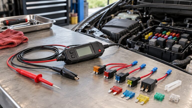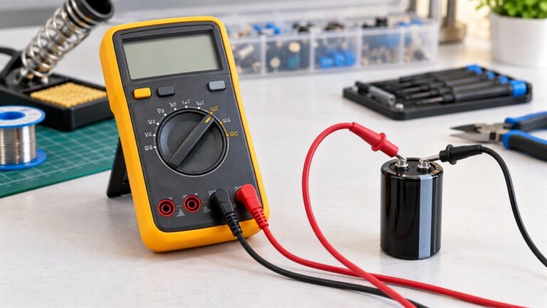
Relay Test
As an Amazon Associate we earn from qualifying purchases. Details
A relay is a small electrically operated switch. A low-current coil on one side closes a contact that carries a larger load on the other, which is why a relay sits behind fuel pumps, horns, fan motors and headlights. A relay test answers one question: does the coil energize, and do the contacts open and close as they should? You can answer it with a multimeter and a 12V source, or with a dedicated relay tester. This guide covers both routes for the common 4-pin and 5-pin 12V automotive relay, shows what each reading means, and compares three relay testers using the text on their listings.
Quick answer
With a multimeter, measure resistance across the coil terminals (85 and 86), then check continuity across the switch terminals with the coil off and again with the coil powered from a 12V source. A good coil reads a steady resistance, not open and not near zero. The contacts should change state when the coil is energized, and you should hear a click. If you test relays often, a self-contained tester gives a pass or fail in one button press, but each listing below states which relay types it covers, so check the pin count first.
What the four or five pins do
Most automotive relays follow the same numbering. These roles come from an engineering guide we opened (linked in Sources); check the relay’s own markings or datasheet, because not every relay follows the standard layout.
| Pin | Role | Present on |
|---|---|---|
| 85 | Coil terminal, usually the negative or ground side | 4-pin and 5-pin |
| 86 | Coil terminal, receives the positive control voltage | 4-pin and 5-pin |
| 30 | Common terminal, connects to the load side | 4-pin and 5-pin |
| 87 | Normally open: joins pin 30 only while the coil is energized | 4-pin and 5-pin |
| 87a | Normally closed: joins pin 30 while the coil is not energized | 5-pin only |
A 4-pin relay is a simple on-off switch. A 5-pin relay is a changeover switch: pin 30 sits on 87a at rest and moves to 87 when the coil is powered. That difference matters when you choose a tester, because the three relay testers below are all listed for 4- and 5-pin relays, but none of the listings covers other layouts.
Test a relay with a multimeter
You need a multimeter with resistance and continuity functions, two jumper wires, and a 12V source such as a car battery. Take the relay out of its socket first. Check the battery too: the first tester listing below states a working window of 11V to 15V, so a battery that has sagged to 10V is outside what that listing allows. If you want a meter for this job, our guide to auto-ranging digital multimeters lists options, and the continuity tester guide covers simpler tools.
Step 1: Look at the relay
Check the housing and terminals for cracks, melted plastic, green corrosion or bent blades. Read the markings on the case: the pin numbers, the coil voltage and the contact layout. A relay built for a different voltage or with a different layout will not give meaningful results on a 12V bench test. A 24V truck relay, for example, should not be powered from a 12V battery, and a relay marked for 6V should not be powered from 12V either. The engineering guide we read says to verify the coil’s rated voltage before applying power.
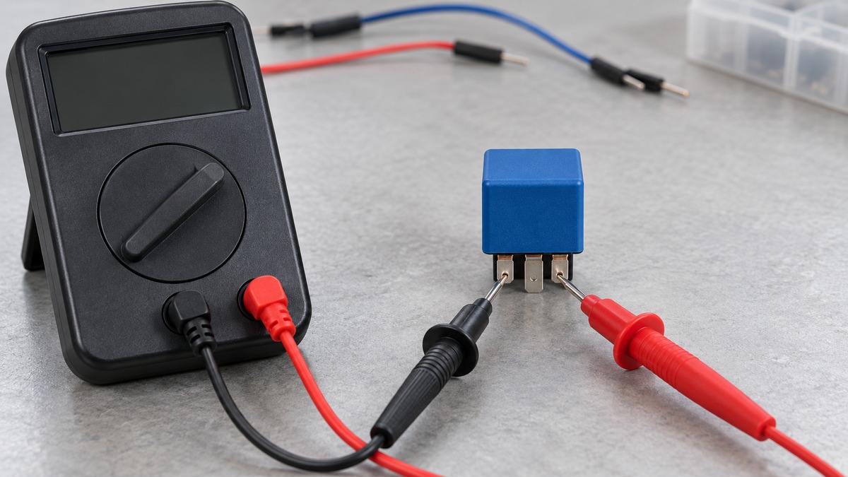
Step 2: Measure the coil resistance
Set the multimeter to ohms and probe pins 85 and 86. Polarity does not matter for a resistance reading on a plain coil. The engineering guide we read gives about 50 to 200 ohms as a typical range for automotive 12V relays, with many sitting around 80 to 110 ohms. Treat that range as a general guide and compare against the specification printed for your relay if there is one.
- Open reading (OL or infinity): the coil winding is broken. The relay will not click when powered.
- Near-zero reading: the coil is shorted. The same source notes a shorted coil can blow fuses when powered.
- A steady reading in the expected range: the coil winding is intact. This does not yet show the contacts work.
Some relays include a diode or a resistor across the coil. These can change the reading depending on the direction of the meter leads. If you get a different value after swapping the probes, check the relay’s datasheet before judging it.
Step 3: Check the contacts with the coil off
With nothing connected to 85 and 86, set the meter to continuity. Probe 30 to 87: a healthy relay shows no continuity because 87 is normally open. On a 5-pin relay probe 30 to 87a: the meter should show continuity because 87a is normally closed. Continuity on 30 to 87 with the coil off points to contacts that are stuck closed.
Step 4: Power the coil and check the contacts again
Connect your 12V source with a positive lead to pin 86 and a negative lead to pin 85. The engineering guide stresses checking the coil’s rated voltage before applying power. When the coil is energized you should hear a click. With the coil powered, probe 30 to 87: continuity should now appear. On a 5-pin relay, 30 to 87a should now read open.
If there is a click but no continuity from 30 to 87, the contacts are not closing and the relay should be replaced. If the reading comes and goes when you tap the case, treat the relay as suspect and repeat the test with a second relay of the same type.
Step 5: Read the load side, not just the coil side
A continuity reading only says the contacts touch. The same guide suggests a functional check: with the relay powered through 86 and 85, measure DC volts at pin 87 and confirm battery voltage passes from pin 30. This is a stronger check than continuity alone.
Testing the relay in the car
You can also check the relay socket instead of the relay. With the circuit switched on, probe the socket terminals for battery voltage at the pin that feeds the load (30) and for the switched coil feed at 86, and check that the coil ground at 85 is a good ground. This shows whether the fault is the relay or the wiring around it. The engineering guide advises disconnecting power before testing in a circuit and verifying the coil’s rated voltage first. A 12V test light, such as those in our 12V tester light guide, can do the same job as a meter for a quick power or no-power check.
Interpreting the results
| What you see | Likely meaning | Next step |
|---|---|---|
| Coil reads OL | Open coil winding | Replace the relay |
| Coil reads near zero | Shorted coil winding | Replace the relay and check the fuse |
| Coil in expected range, no click when powered | The coil may not be getting enough voltage, or the relay has failed mechanically | Check the 12V source and wiring; try another relay |
| Click, but no continuity from 30 to 87 | Burnt or broken contacts | Replace the relay |
| Continuity from 30 to 87 with the coil off | Contacts stuck closed | Replace the relay |
| Passes on the bench, fault remains in the car | Problem is in the wiring, socket or load | Test the socket terminals |
A planning example
Suppose the coil reads 90 ohms between pins 85 and 86. On a 12V supply the coil draws about 0.13 amps (12 divided by 90, roughly 133 milliamps). That is a small current, which is why a relay can switch a heavy load without a thick control wire. Now suppose a different relay reads 12 ohms on the coil. The same sum gives 1 amp, about eight times the current. That reading is also below the 20 ohms that the first tester listing below calls the preferred minimum for coil resistance, so that tester may not suit it. Compare any unusual reading with the relay’s specification before replacing anything.
Relay testers compared
A dedicated tester saves time when you have many relays to check. The three listings below were read on 17 October 2026. We did not test any of them. Details come from each listing’s title, bullets and description.
| Listing | Relay types listed | Power source | Result display | Extras listed |
|---|---|---|---|---|
| Sound Troubleshooting relay tester with puller | 4-pin and 5-pin, switch selects | Clips to a 12V car battery, 11V-15V | Green LED normal, red LED abnormal | Relay puller and battery clips |
| Performance Tool 3009 | 12 volt 4-pin and 5-pin | 4 AA batteries included, no battery clips needed | Green LED pass, red LED fail | None listed |
| Sound Troubleshooting relay tester with battery and alternator check | 4-pin and 5-pin | Not stated | Lights, plus audible indicators | Battery clamps for a battery and alternator check |
1. Sound Troubleshooting relay tester with relay puller (B0DSM43JZV)
Best for: checking relays on a bench or at the vehicle when you want a puller in the box.
Skip if: you cannot clip to a 12V battery. The listing says the tester must connect to a battery between 11V and 15V.
Listed specs: automatic detection of pin position, release time and consistency of the relay through each test phase. You clip the red lead to the positive terminal and the black lead to the negative terminal, set the 4 Pin or 5 Pin switch, insert the relay in the matching socket and press the Test button. The listing says applicable coil resistance is preferably above 20 ohms. It also says the tester is not intended for use with all BMW relays.
2. Performance Tool 3009 cordless relay tester (B0CB711FNB)
Best for: bench testing relays with no battery clips.
Skip if: your relays use wide blade terminals. One buyer comment on the listing says it does not work on wide-spade relays. The listing itself says it tests the most common 12 volt 4-pin and 5-pin relays.
Listed specs: self-contained, powered by 4 AA batteries that are included. The description says it checks the relay coil for circuit breaks and the switch contacts, with a switch on the face for different relay configurations. It tests relays outside the vehicle.
3. Sound Troubleshooting relay tester with battery and alternator check (B0FNTBJ97J)
Best for: a single tool that checks relays and also gives a basic battery and alternator check.
Skip if: you need a stated battery voltage range or coil resistance limit. The text we read does not give either, and it does not repeat the BMW exclusion that the first listing states. Confirm both with the seller if they matter to you.
Listed specs: plug in the relay and press the TEST button; lights and audible indicators show the result. The listing says the included clamps connect to the vehicle battery to verify the battery is charged and the alternator output is correct, but it gives no voltage thresholds.
Where the listings disagree
The first and third listings share a brand and a patent claim but describe power differently: the first connects to a battery for the test, and the third mentions battery clamps for the battery and alternator check without saying whether the relay test uses them. The Performance Tool listing is the only one that says it needs no clips. Because these points are not settled on the listings, we show both rather than pick one.
Multimeter or relay tester?
A multimeter reads the coil resistance, which a plain pass or fail tester does not show, and it also lets you probe the socket in the car. A relay tester is faster when you have a row of identical relays to sort. Some buyers simply swap in a known-good relay of the same type as a first check. That costs nothing but proves little about why the first relay failed. Use whichever approach suits the job and, if a result looks odd, repeat it with the other method.
Frequently asked questions
How do I know if a relay is bad?
Measure the coil between 85 and 86 for an open or near-zero reading, then check that pin 30 joins pin 87 only when the coil is powered. A relay that clicks can still have bad contacts, so the click alone does not prove it is good.
Can I test a relay without removing it?
You can probe the socket for voltage and ground, but a resistance or continuity test of the relay itself needs the relay out of the circuit or the coil isolated. The engineering guide we read advises removing power first.
What coil resistance is normal for a 12V relay?
The guide we read gives about 50 to 200 ohms as a typical range, with many near 80 to 110 ohms. Use the relay’s specification when it is available.
Do all relay testers work on every relay?
No. The three listings above cover 4-pin and 5-pin 12V relays. One states it is not intended for all BMW relays, and one buyer comment mentions wide-spade relays as a poor fit. Check your relay type against the listing.
Is a bench test enough?
A bench test shows whether the relay itself works. If the circuit still fails with a good relay, move to the socket, the fuse and the wiring. Our continuity tester guide can help with wire checks.
Related guides
For checking wires and switches, read Best Continuity Tester. For a meter to measure coil resistance, see Best Auto Ranging Digital Multimeter. For a quick power check at the socket, read Best 12v Tester Light.
Sources
- Wevolver, How to Test a Relay: Comprehensive Engineering Guide: used for the pin roles, typical coil resistance range, the contact checks, and the advice to verify coil voltage and remove power before testing in a circuit.