How to Test Headphones With a Multimeter
As an Amazon Associate we earn from qualifying purchases.
How to test headphones with a multimeter comes down to two bench checks, done with the headphones fully disconnected from any device and any power source: continuity along each conductor from the plug to the driver, and resistance across each driver. The sources checked for this page describe these checks for cables and components in general. They do not give a headphone-specific procedure, a plug wiring map, or a resistance value for any driver.
Electrical safety
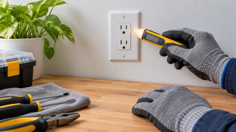
Work on mains circuits can kill. Before you measure anything, check that the meter’s CAT rating suits the circuit you are testing, and read the rating from the listing or the manufacturer’s manual. Panel and service work belongs to a licensed electrician.
The checks in this guide are low-voltage bench work on unpowered headphones. They do not cover a connected amplifier, phone, computer, or any outlet, and no step here asks you to measure a live circuit.
The rule is about current as well as voltage. Iowa State University’s environmental health and safety page says an electrical shock injury can occur at a current as low as 10 milliamperes, and that exposure at 80 to 100 mA can be fatal. The Cal Poly environmental health and safety page gives the same figures. The University of Washington multimeter guide says voltages above 60 V DC or 30 V AC rms pose a shock hazard, and Fluke’s safety guide says shock occurs when the human body becomes part of an electrical circuit. Fluke’s safety guide also advises treating every component as energized until it has been positively discharged.
Meter damage is the second risk. Fluke’s automotive continuity guide warns that testing powered circuits in continuity or resistance mode can damage the meter. The University of Washington guide says never to measure resistance in a circuit when power is applied.
CAT ratings are categories, each paired with a voltage. Fluke’s IEC category article lists CAT I for protected electronic equipment, CAT II for single-phase receptacle-connected loads such as appliances and portable tools, CAT III for 3-phase distribution and equipment in fixed locations, and CAT IV for the utility connection. Fluke’s safety guide says to choose a meter rated for the highest category you could potentially use it in, with a voltage rating that matches or exceeds that situation, and that the ratings are usually located near the input jacks. Fluke also notes that CAT ratings have no relation to the PPE hazard risk categories in NFPA 70E, so the two should not be mixed up. This guide names no meter, so no CAT rating for a specific meter is stated here.
Quick answer
- Power first: the headphones must be unplugged from every device and every power source, and the meter must be set to continuity or resistance on the bench.
- Continuity: a beep with a low reading means a closed path along a conductor. No beep with OL means an open path or very high resistance.
- Driver resistance: read each driver with the component out of the circuit where possible. The sources checked give no DC value to compare the reading against.
How we chose
The steps come from pages on continuity and resistance measurement that were opened with curl on 2026-10-22. Each procedure line below traces to a quote or paraphrase from a page listed at the end of this guide. Pages that returned 403, 404, 405 or 429 were not counted. Forum threads, retailer tutorials, and search snippets were not used as evidence for any step.
Three rules decided what stayed in. A step stayed only if an opened page states it, or states the rule behind it. A safety claim stayed only if at least three opened pages support it, and the three CAT points come from three Fluke pages that share one publisher. A number stayed only if an opened page gives it, with the page named beside it. The sentence that panel and service work belongs to a licensed electrician is a site rule for scope, not a claim taken from a source.
Preparation
- Discharge any capacitor before taking a resistance reading. Fluke’s resistance guide gives this as a step, and the University of Washington guide gives the same rule.
- Disconnect the headphones from the device, any amplifier, and any battery or other power source. Fluke’s automotive guide says to disconnect battery power or isolate the circuit before a continuity test.
- Check the meter and the leads before use. The University of Washington guide says never to use the meter if the meter or the test leads look damaged, and to replace the battery as soon as the battery indicator appears.
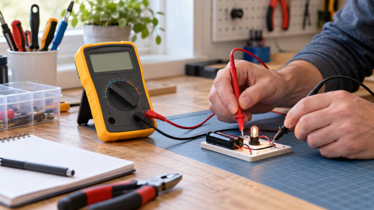
- Plug the black lead into COM and the red lead into V/Ω. Fluke’s automotive guide gives this layout. The University of Washington guide says it is critical that the leads sit in the right jacks for the measurement, and calls wrong lead placement when switching between current and other modes the most common mistake.
- Before a low-value reading, touch the leads together and check the display. Fluke’s resistance guide says lead resistance is typically 0.2 Ω to 0.5 Ω, and that the display should show 0 Ω when the leads are shorted together. Its relative (REL) mode subtracts lead resistance automatically.
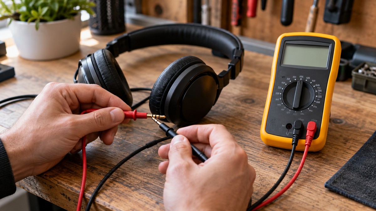
Step 1: check continuity along each conductor
- Set the dial to Ω and press the continuity button so the meter beeps on a closed path. Fluke’s automotive guide gives this setup, and notes that the display also shows a resistance reading.
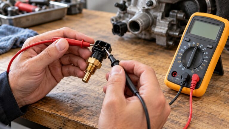
- Touch one probe to one end of the conductor and the other probe to the far end. Fluke’s automotive guide lists “end-to-end on a wire harness” as one use of this check. The University of Washington guide says continuity mode checks whether two points are electrically connected, and that it is often used to verify connectors.
- Read the result. A beep with a low reading means a closed path. Fluke’s automotive guide says no beep with OL or a high reading points to an open circuit or very high resistance, which can come from a break, corrosion, or a bad connection.
- Test one path at a time, between the two points you want to compare. Fluke’s automotive guide lists single paths such as across a fuse, across switch terminals, and end-to-end on a wire harness.
The sources checked do not say which plug contact connects to which driver terminal. Identify each pair with the manufacturer’s wiring diagram, or by testing each contact in turn.
Step 2: measure the resistance of each driver
- Confirm that the power is off and that no power source is connected. Fluke’s resistance guide lists turning off power to the circuit as its first step.
- Set the dial to Ω. Fluke’s resistance guide says the ohms position often shares a dial spot with continuity, diode, and capacitance modes.
- Connect the test leads across the driver’s two terminals. Fluke’s resistance guide says to connect the leads across the component being tested, with good contact between the leads and the circuit. In autorange mode, Fluke’s guide says the meter adjusts its range once the leads connect to a component.
- Remove the driver from the circuit if you can. Fluke’s resistance guide says the best results come when the component is removed, because other components in parallel can change the reading, usually lowering it. Where a part sits on a circuit board, the same guide says it may be necessary to lift one lead to read the part alone.
- Read the display after it settles. Fluke’s resistance guide says an OL display before the leads touch anything is normal in resistance mode. Fluke also says caution is required when measuring resistance across a component that is part of a circuit.
Reading the results
The beep threshold differs between sources. Fluke’s automotive guide says a beep typically means resistance below about 25 to 50 ohms. The University of Washington guide gives 210 ohms for the meter it describes. Check your meter’s manual before you read a beep as a value, and use the Ω display for the number.
Fluke’s automotive guide gives a near-zero reading, about 0.0 to 0.2 ohms, as good continuity. That example comes from automotive wiring, so it does not set a target for a headphone driver.
Fluke’s resistance guide says the meaning of a resistance reading depends on the component being tested, and that the resistance of any one component varies over time and from component to component. It adds that slight changes are usually not critical but may show a pattern worth noting. The sources checked do not give a baseline for any driver.
The sources checked do not say what resistance a headphone driver should read. Shure’s impedance guide defines impedance as the opposition a device offers to an AC current, such as an audio signal. A listed impedance is therefore an AC figure, and the sources checked do not say how a multimeter’s ohm reading compares with it. Compare a reading with a listing only after you confirm how the listing defines its figure.
Fluke’s automotive guide ties an open reading to a break or a very high resistance in the path. The sources checked do not describe what a near-zero reading means across a driver.
Common mistakes
- Testing a powered circuit in Ω or continuity mode. Fluke says this can damage the meter, and the University of Washington guide says the same for resistance with power applied.
- Measuring a driver while it is still wired into other parts. Fluke’s resistance guide says parallel paths change the reading, and advises checking the circuit schematic for them.
- Skipping the capacitor discharge. Both Fluke’s resistance guide and the University of Washington guide state the rule.
- Leaving lead resistance in a small reading. Fluke puts typical lead resistance at 0.2 Ω to 0.5 Ω.
- Touching the metal probe tips. Fluke’s resistance guide says the human body becomes a parallel path that lowers the total reading.
- Measuring over dirt, solder flux, or oil on the contacts. Fluke’s resistance guide lists these as factors that can affect resistance readings.
- Probing carelessly near electronic parts. Fluke’s automotive guide warns that static discharge or improper probing can also cause damage, so take care with headphones that contain electronics.
- Treating the beep as the measurement. Fluke’s automotive guide says continuity mode gives both a beep and a resistance reading, so the number is on the display.
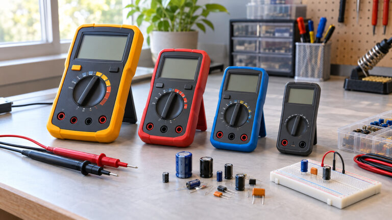
For the meter itself, read the guide to using a continuity tester and the roundup of ohm meters. A related continuity check on a component is covered in checking a fuse with a multimeter.
What we could not verify
The sources checked do not cover these points, and this guide does not answer them:
- A resistance value for any headphone driver. No headphone listing or manual was opened for this page, and the Shure page that was opened describes impedance without giving a DC figure.
- The wiring of any particular plug. The sources checked do not state which contact connects to which driver.
- Wireless headphones, active noise cancelling circuits, and in-ear designs with several drivers and crossover parts.
- A CAT rating for any specific meter. This guide names no meter, and the listing does not state one here.
- The beep threshold on your own meter. The two sources give different figures, so the manual decides it.
- Electrician licensing rules in your area. The sources checked do not cover them.
FAQ
Can I test headphones while they are plugged into my phone?
No. This method needs the headphones fully disconnected. Fluke says to disconnect battery power or isolate the circuit before a continuity test, and the University of Washington guide says an external voltage across a component gives invalid resistance readings.
Why does my meter beep at one value and not another?
The two sources checked give different beep thresholds, roughly 25 to 50 ohms for Fluke’s automotive example and 210 ohms for the University of Washington meter. Your meter’s manual states its own threshold.
What does OL mean on the display?
In Fluke’s automotive guide, OL with no beep points to an open circuit or very high resistance. In resistance mode, Fluke’s guide says the OL display is expected before the leads touch anything.
Do I need to remove the driver from the earphone before I test it?
Fluke’s resistance guide says the best results come with the component out of the circuit, since parallel parts can alter the reading. The sources checked do not describe how to open an earphone or headphone, so that work is outside this guide.
Does a continuity beep show that the headphones work?
No. A beep shows only that the meter found a low-resistance path between two points. The sources checked do not say that a continuity pass proves a driver produces sound.
What resistance should a headphone driver read?
The sources checked do not give a DC resistance for any driver. Check the manufacturer’s listing or manual for a stated impedance, and remember that Shure’s guide treats impedance as an AC figure.
Sources
- Fluke, How to Measure Resistance with a Digital Multimeter: https://www.fluke.com/en-us/learn/blog/digital-multimeters/how-to-measure-resistance
- Fluke, How to Perform Automotive Continuity Checks with a Multimeter: https://www.fluke.com/en-us/learn/blog/digital-multimeters/how-to-perform-automotive-continuity-checks-with-a-multimeter
- Fluke, Guide to digital multimeter safety: https://www.fluke.com/en-ie/learn/blog/safety/multimeter-guide
- Fluke, IEC Category Ratings: Use the Right Tools for the Job: https://www.fluke.com/en-us/learn/blog/safety/iec-category-ratings-use-the-right-tools-for-the-job
- Fluke, IEC Category Ratings (knowledge base KA-03314): https://my.fluke.com/en-us/article/KA-03314
- University of Washington, ESS 205 Multimeter and Breadboard Guide: https://pita.ess.washington.edu/wp-content/uploads/sites/4/2016/04/multimeterguide.pdf
- Iowa State University, Environmental Health and Safety, Electrical Safety: https://www.ehs.iastate.edu/node/51
- Cal Poly, Environmental Health and Safety, Electrical Safety: https://afd.calpoly.edu/ehs/electricalsafety
- Shure, Earphone and headphone specifications explained: https://www.shure.com/en-US/insights/earphone-headphone-specifications-explained