How to Choose a Multimeter for Checking Relays
As an Amazon Associate we earn from qualifying purchases.
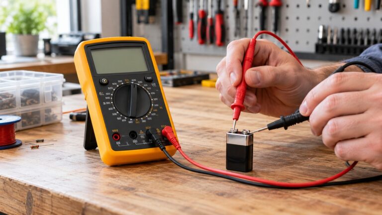
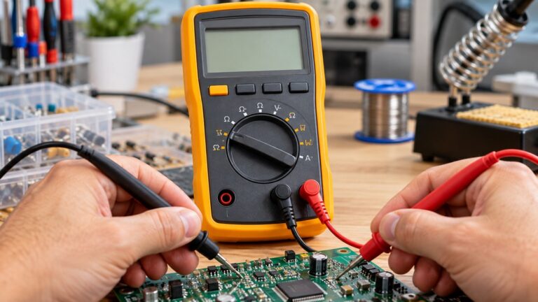
Learning how to choose a multimeter for checking relays comes down to three things: an ohms range that reads a relay coil, a continuity beep that shows whether the switch contacts close, and a CAT rating that suits the circuit you work on. The checks described in the sources are low-voltage bench or vehicle tests, with the coil energized from a 9 V or 12 V source and the meter reading resistance and continuity.
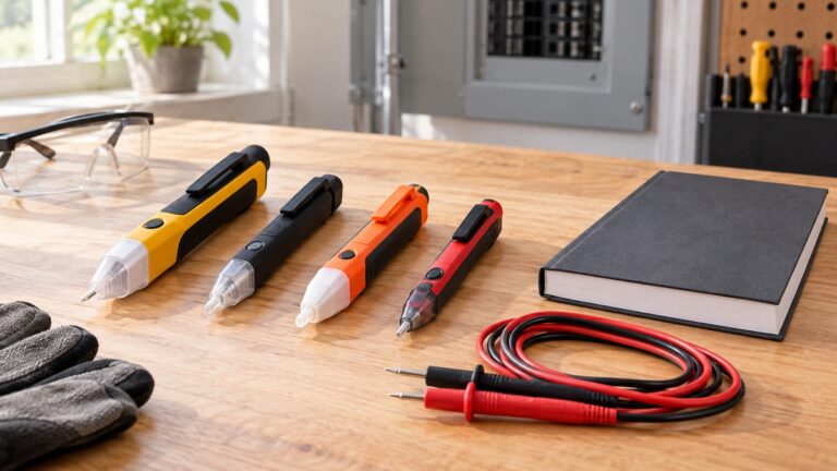
Electrical safety first
Work on mains circuits can kill. The background pages we opened describe the same risk in different terms. One says no person can be sure of not being killed “even from a 110-volt circuit” if the contact path lets maximum current pass through the body. A second says “death is possible” at higher current levels. A third states that for death to occur, the human body must become part of an active electrical circuit. They are background sources, not standards.
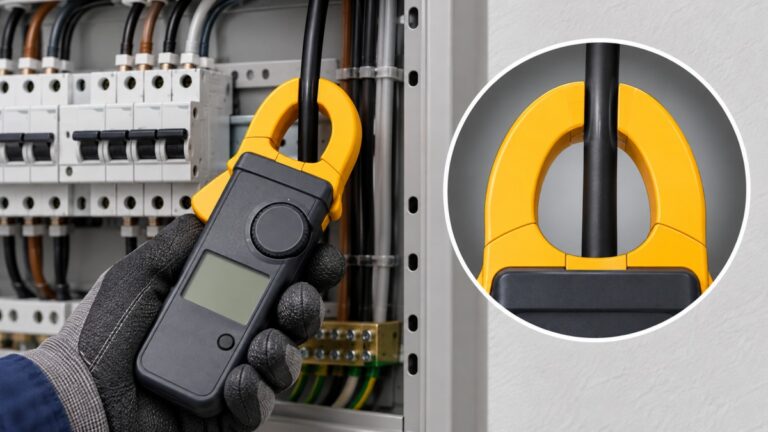
Before you measure anything, check that the meter’s CAT rating suits the circuit you are testing, and read the rating from the listing or the manufacturer’s manual. The Fluke 175 listing says its inputs are “protected to IEN61010-1 CAT IV 600 V/CAT III 1000 V.” The Fluke 177 listing says “Safety rated CAT III 1000 V, CAT IV 600 V.” The Fluke 179 listing gives “CAT III 1000 V, CAT IV 600 V” as its input protection rating. The Fluke 87V listing says its inputs were updated to “CAT III 1000 V and CAT IV 600 V.” The Fluke 117 listing describes the meter as “CAT III 600 V.” The listings we opened do not explain what each category means for a given circuit, and they do not replace the manufacturer’s manual.
Panel and service work belongs to a licensed electrician. This is the rule for this site. None of the sources we opened state it, so it is site policy, not a sourced fact. Relay checks in this guide stay on low-voltage bench and vehicle circuits, and they do not cover panels, outlets or service wiring. The relay sources also say to remove power before testing. One says to “be sure to de-energize your relay by removing power to it,” and another says to “Always disconnect power before testing.”
Quick answer
- Pick a meter with an ohms function that can read a relay coil. The sources put the usual automotive coil range at roughly 50 to 200 ohms.
- Pick a meter with continuity mode, because the contact checks depend on a beep.
- Check the CAT rating in the listing or manual.
- Count the relay pins before you test. A 5-pin relay has a normally closed terminal, pin 87a, that a 4-pin relay lacks.
What a relay check asks of the meter
Most automotive relays use the same numbering. The coil is on pins 85 and 86. The main power input is pin 30. Pin 87 is the normally open terminal, which connects to pin 30 only when the coil is energized. On a 5-pin relay, pin 87a is the normally closed terminal, which connects to pin 30 when the coil is not energized. The Wevolver guide puts it this way: pin 87 is “Connected to 30 only when the coil is energised,” and pin 87a is “Connected to 30 when the coil is not energised.” A 4-pin relay has no pin 87a.
Markings differ on printed circuit board relays. The Etechnophiles guide says that in a PCB relay “there are no such markings,” so check the relay’s own datasheet before you assume the pin roles above.
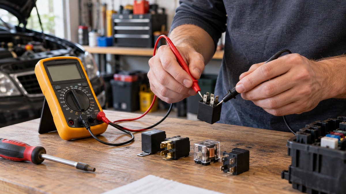
That gives the meter three jobs: read the coil resistance on pins 85 and 86, check continuity between pin 30 and the contacts with the coil off, and check continuity again while 12 V is applied to the coil. The features below follow those three jobs.
Features that matter for relay checks
An ohms range that reads 50 to 200 ohms
The coil check is a resistance reading. The Wevolver guide gives “coil resistance between 50 and 200 ohms” for automotive power relays. The Friday Parts guide gives “between about 50 and 120 ohms,” and it tells you to “use the 200Ω range” if your meter has several ranges. The Drive article gives “between 50 and 120 ohms” and calls a reading outside that window “out-of-spec.” A meter that can select a range near 200 ohms covers each of these figures.
The sources do not agree on one number, so the coil window is a guide only. The relay’s datasheet or the vehicle’s service information gives the rated coil resistance for a specific part. When a reading falls between the published figures, the sources we opened do not say whether the coil is good or bad.
Continuity mode with an audible beep
The contact check depends on a beep. The Friday Parts guide says to “Set your multimeter to continuity mode,” and it describes the meter beeping when there is a complete connection between the probes. The Etechnophiles guide checks continuity between the normally closed terminal and the common terminal with the coil off, then checks the normally open terminal against the common terminal with the coil energized. The steps as written need a continuity function.
Auto-ranging or manual ranging
The Etechnophiles guide says that when setting the coil range, “if you have an auto-ranging multimeter, skip this part.” The sources we opened do not say whether auto-ranging changes the accuracy of a relay check.
Display counts and resolution
Two listings state a 6000-count display. The Fluke 177 listing says “6000-count resolution,” and the Fluke 87V listing says “6000 counts.” The relay sources do not say how many counts a relay check needs, and the listings we opened do not state a count for the Fluke 175, 117 or 179.
Backlight and display readability
The Fluke 177 listing describes “digital display with backlight for working in dim lighting.” The Fluke 117 listing describes “a bright backlight for darker worksites.” The Fluke 179 listing says “backlit digital display,” and the Fluke 87V listing describes a “two-level backlight.” The Fluke 175 listing does not say whether its display is backlit. The sources do not say that a backlight improves relay test accuracy.
True RMS
The Fluke 117, 175, 177, 179 and 87V listings all describe true-RMS meters. The relay procedures use a 9 V or 12 V coil supply and do not discuss RMS for this check, so whether it matters here is an open question.
Listed specs for the meters we opened
A cell says “not stated” when the page we opened gives no figure.
| Listing | CAT rating stated | Display counts stated | Continuity or diode stated | Backlight stated | Non-contact stated |
|---|---|---|---|---|---|
| Fluke 175 | CAT IV 600 V / CAT III 1000 V | not stated | Yes | not stated | not stated |
| Fluke 177 | CAT III 1000 V, CAT IV 600 V | 6000-count resolution | Yes | Yes | not stated |
| Fluke 179 | CAT III 1000 V, CAT IV 600 V | not stated | Yes | Yes | not stated |
| Fluke 87V | CAT III 1000 V, CAT IV 600 V | 6000 counts | Yes | Yes | not stated |
| Fluke 117 | CAT III 600 V | not stated | not stated | Yes | Yes |
How we chose
The criteria in this guide come from the relay steps in the sources we opened. A feature appears here only when a source ties it to a relay step, or when a listing states it for a meter. The evidence is four relay procedure pages from an engineering site, a parts seller, a blog and an automotive writer, plus five manufacturer listing pages for Fluke meters, all opened on 2026-10-21. The meters are not ranked against each other.
Several pages returned errors when we opened them. The Omron and TE relay pages returned 403, and the Finder relay page returned 404. We left these out of the evidence, so the sources in this guide do not represent every relay maker’s datasheet.
Test steps the sources describe
These steps use a 12 V source for the coil, which is low voltage. Check the relay’s rated coil voltage before you apply power, because the Wevolver guide says to “verify the relay’s rated coil voltage before applying any power.”
- Coil resistance: Set the meter to ohms, touch the probes to pins 85 and 86, and read the value. The sources give 50 to 120 ohms or 50 to 200 ohms as the usual range.
- Contacts with the coil off: Set the meter to continuity. On a 4-pin relay, test pins 30 and 87. The Friday Parts guide says an open reading there is normal, because pin 87 is normally open. On a 5-pin relay, test pins 30 and 87a. That pair should beep, because pin 87a is normally closed.
- Coil energized: Connect 12 V to the coil. The Friday Parts guide says a healthy relay gives “a clear ‘click.'” Keep the coil energized and test pins 30 and 87 again. This time the pair should beep.
The sources describe these steps for a relay on the bench. They do not give a separate step for a relay still mounted in a vehicle, so remove power before you start.
Reading the results
- OL or infinite resistance on the coil: The Friday Parts guide says this means the coil is open or broken inside. The Wevolver guide says “An open coil will show an infinite or “OL” reading.”
- Near 0 ohms on the coil: The Friday Parts guide says a reading of 0 ohms or very close to 0 means the coil is shorted internally.
- Beep with the coil off on pins 30 and 87: The Friday Parts guide says the contacts are stuck closed and the relay is bad.
- No click when the coil is powered: The Friday Parts guide says “No click usually means the coil is bad or the relay is stuck.”
- Contact resistance: The Wevolver guide says “New automotive relays often show contact resistance below 50 milliohms,” and that “Rising or unstable resistance can indicate wear or contamination.” The sources do not give a pass or fail figure for a contact-resistance reading on a multimeter.
Common mistakes
- Testing a relay that still has power applied. The Wevolver guide says “Always disconnect power before testing.” Remove power first, and energize the coil only in the step that calls for it.
- Treating one coil range as the rule. The sources differ, with 50 to 120 ohms in some and 50 to 200 ohms in others. Use the relay’s datasheet when you have it.
- Reading a beep as proof of a healthy contact. The continuity beep shows a closed path. The Wevolver guide also says contact resistance can rise or become unstable with wear, and a beep does not show that change.
- Using a 4-pin expectation on a 5-pin relay. A 4-pin relay has no pin 87a. Count the pins on the part you hold before you run the continuity steps.
- Ignoring the CAT rating. Check the rating in the listing or manual before you use the meter on any circuit beyond these low-voltage steps.
Buying checklist
- An ohms range that can read roughly 50 to 200 ohms.
- A continuity mode with an audible beep.
- A stated CAT rating that suits the circuit you work on, read from the listing or manual.
- A display you can read where you work. Check whether the listing states a backlight.
- A stated count or resolution, if you need finer steps. The relay sources do not say a count is required.
- Leads with a stated rating. The listings we opened do not state lead ratings for these meters, so check the leads separately.
What we could not verify
The sources we opened do not give a manufacturer’s coil resistance for any specific relay part. They do not state a contact-resistance pass or fail value for a multimeter check. The listings do not state a minimum resistance resolution for relay contacts, and they do not say whether any listed meter suits a particular relay. The sources disagree on the coil resistance window and do not reconcile it.
What the sources do not say
The sources we opened do not say how a relay check changes with coil voltages other than 9 V or 12 V, and they do not discuss solid-state relays.
FAQ
Do I need a meter with a continuity beep to check a relay?
The contact steps in the sources depend on a beep, so a meter without continuity mode cannot run them as written. The coil reading still works with a plain ohms function.
What coil resistance should I expect?
The sources give 50 to 120 ohms in some cases and 50 to 200 ohms in others. The relay’s datasheet is the reliable source for a specific part.
Why does a 5-pin relay need a different test from a 4-pin relay?
A 5-pin relay has pin 87a, a normally closed terminal that connects to pin 30 when the coil is off. A 4-pin relay has no 87a, so the normally closed check does not apply to it.
What does an OL reading on the coil mean?
The Friday Parts guide says it means the coil is open or broken inside.
Does a CAT rating matter for a 12 V relay check?
The sources we opened do not say that a 12 V coil check needs a particular CAT rating. Before you use a meter on any other circuit, check the rating the listing or manual gives for it.
Related guides
For the full step-by-step relay test and relay tester comparison, read the relay test guide. For the range and display types you will see across models, compare the auto-ranging digital multimeter roundup with the hand-held digital multimeter roundup.
Sources
- https://www.wevolver.com/article/how-to-test-a-relay-comprehensive-engineering-guide
- https://au.fridayparts.com/blog/how-to-test-a-relay-with-a-multimeter
- https://www.etechnophiles.com/test-relay-with-multimeter/
- https://www.thedrive.com/maintenance-repair/36048/how-to-test-a-relay.md
- https://www.fluke.com/en-us/product/electrical-testing/digital-multimeters/fluke-175
- https://fluke.com.au/en-th/product/electrical-testing/digital-multimeters/fluke-177
- https://www.fluke.com/en-us/product/electrical-testing/digital-multimeters/fluke-117
- https://www.fluke.com/en-us/product/electrical-testing/digital-multimeters/fluke-179
- https://www.fluke.com/en-us/product/electrical-testing/digital-multimeters/fluke-87v
- https://onemine.org/documents/ic-6100-electrical-accident-prevention
- https://www.oshacademy.com/courses/training/809-focus-four-electrocution-hazards/809-1-5.php
- https://www.cochranfirm.com/new-orleans/electrocution/