What Does OL Mean on a Multimeter
As an Amazon Associate we earn from qualifying purchases.
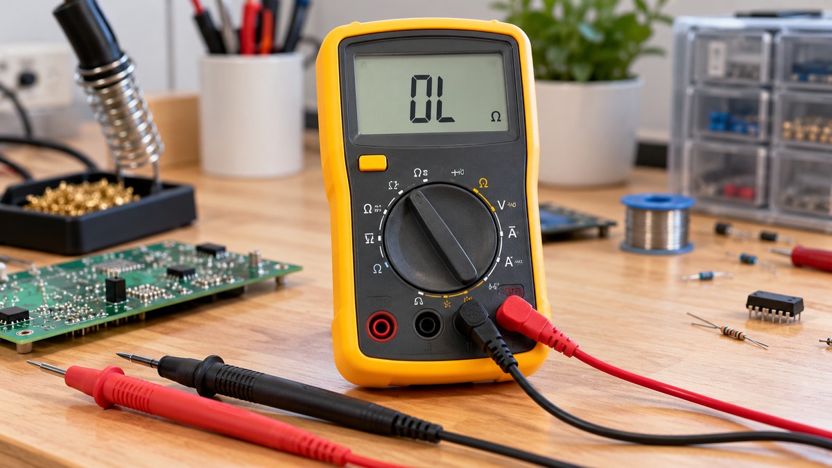
What does OL mean on a multimeter? OL is the display’s overload indication. It appears when the input is beyond what the selected range can show, and in resistance and continuity modes it often means the test path is open or too resistive to read. The manuals we opened use different labels for it, and no single meaning fits every reading or every meter. This article covers resistance, continuity and diode modes, how OL differs from a zero or near-zero reading, and what it cannot tell you on its own.
Electrical safety first
Working on mains circuits can be fatal. Before you take a reading, confirm that the meter’s CAT rating matches the circuit you plan to test, and take that rating from the listing or the manufacturer’s manual. Work on panels and service equipment is for a licensed electrician. The method here is limited to low-voltage bench work, and it leaves out anything done on energized mains, panels, outlets or service wiring.
OSHA’s electrocution training guide states that “Electrocution is fatal; it means to kill with electricity.” OSHA’s general industry rule requires work practices that prevent electric shock, and it requires live parts to be de-energized before an employee works on or near them (OSHA 1910.333). The Klein MM400 manual warns that voltages above 25 V AC RMS or 60 V DC pose a shock hazard.
CAT is the measurement category rating for a meter’s electrical environment. The Fluke CAT explainer places CAT II at single-phase receptacle loads such as appliances, CAT III at fixed three-phase distribution such as switchgear, and CAT IV at the utility connection, including electricity meters and service entrances.
A meter’s own rating comes from its documents. The Klein MM400 manual lists CAT III 600V, and says never to use the meter on a circuit whose voltage exceeds its category-based rating. The Keysight U1281A quick start lists CAT III 1000 V and CAT IV 600 V. The sources we opened do not give a CAT rating for the meter you own, so read that rating from your own listing or manual.
Both Klein manuals, the MM300 and the MM400, tell users not to run resistance or continuity checks on energized circuits. Keysight’s U1281A guide asks you to disconnect circuit power and discharge high-voltage capacitors before a continuity check. The ohms chapter adds that the probes should not touch energized components during a continuity test, because the meter can be damaged.
OL on a voltage range carries a safety meaning as well. The Fluke 287/289 manual says the meter shows its hazardous voltage symbol at 30 V or a voltage overload (OL), and the Keysight quick starts list the same +OL markers in their voltage table. Treat an OL on a voltage range as a hazard warning.
The licensed-electrician rule is this site’s policy, not a sourced fact. The OSHA construction rule says only qualified employees may work on or with exposed energized parts, and the general industry rule requires a qualified person to verify that circuit parts are de-energized.
Quick answer
- OL is an overload indication: the input is beyond the selected range, or the path is open.
- On the Klein meters, OL with the leads open is shown as normal in resistance mode, and the beep threshold varies by model.
- In diode mode, a good diode reads OL with the probes reversed, and an open diode reads OL in both directions.
- On a voltage range, OL can come with a hazardous voltage symbol, so do not read it as a harmless blank.
What OL means on a digital multimeter
OL stands for overload, and most of the manuals we opened use that word or a close variant. The printed label still differs by brand. The Klein MM400 specification lists “OL” as the overload indication, next to overload protection of 600V RMS in all settings. The Fluke 8808A manual prints 0L, a zero followed by L. The HP 34401A user’s guide, a February 1996 document hosted by Purdue, uses OVLD. Its remote interface returns 9.90000000E+37 instead of text, which matters if you log readings by computer. The eCampusOntario resistance chapter notes that the display shows OL or I depending on the manufacturer. In relative percent mode, the Fluke 287/289 manual says the display shows OL at 1000 percent or more.
OL in resistance mode
In resistance mode, OL usually means the value is above what the selected range can show, or that no path closes between the probes. The eCampusOntario resistance chapter says the meter reads infinite (I) or over limit (OL) when the leads are left open. Its ohms chapter goes further and says an infinite or OL reading means the component is open.
The Klein MM300 and MM400 manuals describe O.L. with the leads open, and also with a failed resistor under test. They call that normal, so an OL on its own does not separate an open lead from a failed resistor.
The other end of the scale is zero. The eCampusOntario resistance chapter says the ohmmeter is designed to display 0 Ω when the test leads are clipped together, and that the meter should display zero or a very small amount for the test leads. On the 2000 MΩ range, the CUNY page says shorted leads display 010 because of a fixed offset, and the residual must be subtracted from readings on that range.
Range can also produce OL. The resistance chapter says to switch to the next highest setting when OL appears. The HP guide says an input larger than the present range can measure gives an overload indication, and that its autoranging steps down below 10 percent of range and up above 120 percent. The Fluke 8808A manual says an autoranging meter moves up when a reading exceeds full scale, and displays 0L when no higher range exists. For the range side, see our explainer on the 200 ohms setting, and for auto-ranging meters in general, see our auto-ranging multimeter roundup.
OL in continuity mode
Continuity mode adds a beep threshold. The Klein MM400 manual sounds an audible signal when resistance measures less than 50, and shows “OL” if the circuit is open. The Klein MM300 uses a threshold below 100. The CUNY openlab page gives its beeper a threshold of 40 ohms, plus or minus 20 ohms.
The eCampusOntario continuity chapter says that with the leads apart the meter should display OL or I, and that touching the probes together should sound the audible alarm. It also lists what can break a path: mechanical damage, corrosion of components, or a switch left open. It does not explain how the display tells those causes apart. The Keysight quick starts describe a beeper threshold without giving a number on the pages we opened. For the device basics, see our continuity tester guide.
OL in diode mode
The WKU notes say many digital multimeters can test diodes and measure their forward voltage drop, and that a forward-biased diode acts as a closed switch. The Klein MM400 manual gives 200 to 700 mV on the display for forward bias, and “OL” for reverse bias. The WKU Physics notes place a good silicon diode at about 0.5 to 0.8 volts forward, and say a good diode displays OL when reverse-biased, acting as an open switch in that direction. Probe reversal is therefore expected to produce OL on a good diode.
An open diode shows OL in both directions. The Klein manual, the WKU notes and the CUNY page all describe that pattern.
Near-zero readings vary. The Klein manual says a shorted device shows approximately 0 mV. The WKU notes show the same voltage drop, about 0.4 V, in both directions. The CUNY page shows .000 or another number. The sources do not agree on one value for a shorted diode.
In circuit, a parallel path can distort the reading. The CUNY page says the diode may need to be disconnected for accurate testing, and the WKU notes say one end may need to come out of the circuit.
How OL differs from zero and near-zero readings
The difference is what the meter sees. OL means the reading is beyond the range or the path is open. Zero or near zero means little or no resistance between the probes. The ohms chapter says a zero reading means the component is closed, and on a load it means an internal short.
| Reading | Resistance mode | Continuity mode | Diode mode |
|---|---|---|---|
| OL | Infinite or over limit with the leads open (eCampusOntario resistance chapter) | Circuit open, shown as “OL” (Klein MM400 manual) | Reverse direction on a good diode; both directions on an open diode (Klein MM400 manual; WKU Physics notes) |
| Zero or very small value | Expected with the leads together (eCampusOntario resistance chapter); zero on a load means an internal short (eCampusOntario ohms chapter) | Below the beep threshold, for example under 50 on the Klein MM400 (Klein MM400 manual) | Approximately 0 mV for a shorted device on the Klein MM400; other sources give different values (Klein MM400 manual; WKU Physics notes; CUNY openlab page) |
Common mistakes
- Treating OL as a broken part before checking the range setting. The sources tie OL to a reading above the selected range as well as to an open path.
- Calling a diode bad after one OL reading. A good diode reads OL with the probes reversed.
- Expecting a shorted diode to show one fixed value. The sources disagree on it.
- Ignoring the hazard symbol on a voltage range. The Fluke 287/289 manual ties OL on voltage to that symbol.
- Testing a diode or resistor in circuit without checking for a parallel path.
What OL does not tell you on its own
OL does not identify the cause. It can mean an open path, a value above the range, or, on a voltage range, a voltage overload. The sources we opened do not say how to tell these apart from the display alone. The Klein MM400 warnings link a low battery to false readings and say to replace batteries when the low-battery indicator appears.
OL also does not state the beep point, which is 50 on the Klein MM400, 100 on the Klein MM300 and 40 plus or minus 20 on the CUNY page. In diode mode, one OL does not diagnose a diode. The sources use the pattern across both directions instead.
OL does not say where a break is. The continuity chapter says the test can be applied to a whole circuit or to sections of it, but the pages we opened do not describe how to locate a break along a wire, so this article gives no locating method. OL also does not replace the input limit. The Keysight quick starts warn not to exceed the input limit, and list 1000 Vrms overload protection on the voltage input.
Bottom line
Read OL as an overload or open-path indication, then check the range, the mode and your meter’s manual before deciding what it means. On a voltage range, treat it as a hazard warning first.
How we chose
The pages were chosen by type. Manufacturer manuals and quick starts were included where they state OL behavior: Klein MM300 and MM400, Fluke 287/289 and 8808A, and Keysight U1281A and U1241C. An older HP bench-meter manual, hosted by Purdue, adds the OVLD label. University and college pages cover the concept, OSHA pages cover shock and qualified-person rules, and a Fluke explainer covers CAT categories. All pages were opened on 2026-10-22, and each quoted phrase was checked against the fetched text. Forum threads, SEO articles and reseller guides were excluded. One Fluke how-to blog says a bad diode, open or shorted, displays OL. That conflicts with three other sources on shorted diodes, so it is not used here.
What we could not verify
- No Keysight bench-meter manual was readable. The EDU34450A PDF links returned web pages, so the Keysight points come from handheld quick starts.
- The sources we opened do not say whether a weak battery or poor probe contact produces OL.
- The sources do not give the CAT rating of the meter you own.
- The sources do not say how to tell a range problem from an open path on the display alone.
- The hazard indication on OL in voltage mode was checked only in the Fluke 287/289 and Keysight documents.
Frequently asked questions
Does OL always mean an open circuit?
No. The ohms chapter treats an infinite or OL reading as an open component, but the resistance chapter and the Fluke 8808A manual also describe OL as a reading beyond the selected range. The resistance chapter recommends moving up one range in that case.
Does OL in diode mode mean the diode is bad?
Not on its own. A good diode reads OL when reverse-biased. OL in both directions is the open-diode pattern in the Klein, WKU and CUNY sources.
How is OL different from zero ohms?
OL points to an open path or a reading beyond the range. Zero points to a closed path, and on a load it points to an internal short.
Why does my meter show OL with the leads open?
Both Klein manuals call an O.L. display normal in resistance mode when the leads are open. The same note also covers a failed resistor, so the display alone does not show which case you have.
What does OL mean on a voltage range?
The Fluke 287/289 manual links OL on voltage to the hazardous voltage symbol. Treat the indication as a safety warning, and read your meter’s manual before working on the circuit.
Do all meters show OL the same way?
No. The Klein and Keysight documents use OL, the Fluke 8808A prints 0L, and the HP 34401A shows OVLD. Beep thresholds also differ by model, so your manual is the reference.
Sources
- Klein Tools MM400 instruction manual, opened 2026-10-22: https://data.kleintools.com/sites/all/product_assets/documents/instructions/klein/MM400_1390110ART_WEB.pdf
- Klein Tools MM300 instruction manual, opened 2026-10-22: https://data.kleintools.com/sites/all/product_assets/documents/instructions/klein/MM300_1390109ART_WEB.pdf
- Fluke 287/289 True-rms Digital Multimeters Users Manual, opened 2026-10-22: https://assets.fluke.com/manuals/287_289_umeng0100.pdf
- Fluke 8808A Digital Multimeter Users Manual, opened 2026-10-22: https://media.fluke.com/b37c13c4-2730-4ba0-805d-b10800c2b877_original%20file.pdf
- Keysight U1281A/U1282A Quick Start Guide, opened 2026-10-22: https://www.keysight.com/us/en/assets/9018-19242/quick-start-guides/9018-19242.pdf
- Keysight U1241C/U1242C Quick Start Guide, opened 2026-10-22: https://www.keysight.com/zz/en/assets/9018-04174/quick-start-guides/9018-04174.pdf
- HP 34401A User’s Guide, February 1996, hosted by Purdue University, opened 2026-10-22: https://engineering.purdue.edu/~aae520/hp34401manual.pdf
- eCampusOntario, Multimeters 101: Testing Resistance (Ohms) with a Digital Multimeter, opened 2026-10-22: https://ecampusontario.pressbooks.pub/multimeters101/chapter/testing-resistance-ohms-with-a-digital-multimeter/
- eCampusOntario, Multimeters 101: Introduction to Resistance Measurements, opened 2026-10-22: https://ecampusontario.pressbooks.pub/multimeters101/chapter/1-6-introduction-to-resistance-measurements/
- eCampusOntario, Multimeters 101: Continuity Test, opened 2026-10-22: https://ecampusontario.pressbooks.pub/multimeters101/chapter/continuity-test/
- WKU Physics, Testing Diodes, opened 2026-10-22: http://physics.wku.edu/phys301/notes/dc-circuits/testing-diodes/
- CUNY openlab, Digital Multimeter equipment page, opened 2026-10-22: https://openlab.citytech.cuny.edu/emtlabs/equipment/dmm/
- OSHA 29 CFR 1910.333, Selection and use of work practices, opened 2026-10-22: https://www.osha.gov/laws-regs/regulations/standardnumber/1910/1910.333
- OSHA Training Institute, Construction Focus Four: Electrocution Hazards, opened 2026-10-22: https://www.osha.gov/sites/default/files/electr_ig.pdf
- OSHA 29 CFR 1926.960, Working on or near exposed energized parts, opened 2026-10-22: https://www.osha.gov/laws-regs/regulations/standardnumber/1926/1926.960
- Fluke, IEC Category Ratings: Use the Right Tools for the Job, opened 2026-10-22: https://www.fluke.com/en-us/learn/blog/safety/iec-category-ratings-use-the-right-tools-for-the-job