How to Test a Ferrite Bead With a Multimeter
As an Amazon Associate we earn from qualifying purchases.
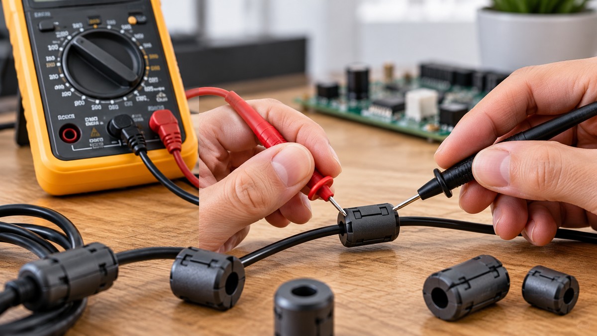
How to test a ferrite bead with a multimeter comes down to two checks, made with the bead out of its circuit and the circuit switched off: a continuity check, which shows whether the bead’s winding or conductor forms a complete path, and a DC resistance reading in ohms. The reading cannot show the filtering impedance that makes a bead useful, because bead data is specified at a stated frequency, usually 100 MHz, and an ohms reading does not measure that frequency.
Electrical safety
Work on mains circuits can kill. Before you measure anything, check that the meter’s CAT rating suits the circuit you are testing, and read the rating from the listing or the manufacturer’s manual. Panel and service work belongs to a licensed electrician.
This method stays on the bench. It covers one bead that has been removed from its circuit, with that circuit switched off. It gives no steps for live mains, outlets, panels or service wiring. The sources we opened do not give a CAT rating or voltage rating for any ferrite bead, so this post states none. Take any rating for a bead from its manufacturer’s datasheet, and take the meter’s CAT rating from the meter’s listing or manual.
The shock risk is the reason the circuit comes first. The Fluke safety guide says “Shock occurs when the human body becomes part of an electrical circuit,” and it tells readers to “Always assume every electrical component in a circuit is energized” until it has been discharged. OSHA’s general industry rule requires safety-related work practices “to prevent electric shock or other injuries” near or on circuits. An OSHA interpretation letter reads the rule as requiring live parts to be “de-energized before an employee works on or near them,” unless that is infeasible.
Fluke’s resistance guide adds a point about capacitors. If the circuit includes a capacitor, discharge it before taking any resistance reading.
Quick answer
- Check the bead with the circuit switched off and the bead removed from it. Fluke and eCampusOntario both describe this order.
- Continuity: a complete path reads low, and an open path reads OL.
- DC resistance: the meter gives one value that includes lead and contact resistance, which Fluke puts at typically 0.2 to 0.5 ohms.
- Filtering impedance: a multimeter does not show it. Renesas says impedance is normally specified at 100MHz.
What a multimeter can and cannot show
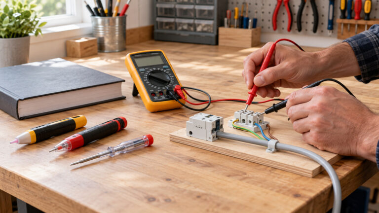
A multimeter in ohms mode sends its own current through the component and measures the result. The eCampusOntario chapter explains that the ohmmeter’s internal battery supplies the current the meter measures. The display is therefore a resistance value at that test current, and it includes the test leads and the contacts. That makes the meter useful for two checks on a removed bead.
- Continuity. A complete path gives a low reading. The eCampusOntario chapter says the meter reads infinite or over-limit resistance when the leads are left open, so an OL reading across a bead means the meter sees no continuous path through it.
- DC resistance. The meter gives one resistance value, which you can compare with the DC resistance stated in the datasheet for the same part, after allowing for lead and contact resistance.
A multimeter cannot show filtering impedance. Renesas says that impedance is “normally measured and specified at 100MHz,” and it advises examining the impedance curves, because impedance characteristics are “material dependent.” A DC ohms reading is not a 100 MHz value, so it cannot confirm the impedance a datasheet promises. The same note says that when a bead operates close to its maximum rating, the impedance “may decrease by half” in some ferrite beads. A bench ohms reading does not put the bead under its operating current, so it cannot show that drop.
A bead’s DC resistance is also a design choice. Renesas says “How much resistance depends on how much voltage drop is allowed,” and it recommends a bead with some DC resistance for a low-pass power filter, while noting that high current power beads should be avoided. A continuity check cannot tell you whether a given bead makes that trade-off correctly.
What you need before you start
- A digital multimeter with an ohms setting and a continuity setting. The Fluke guide says the ohms setting often shares a dial position with continuity, capacitance and diode modes, so check the meter’s manual to find each one.
- The bead, removed from the board or isolated from the circuit. Fluke says the best results come when the component is removed, because other components in parallel can change the reading.
- Clean, firm contact at both ends of the bead. The Fluke guide lists dirt, solder flux and oil as foreign substances that can affect a resistance reading.
- An expected value. The eCampusOntario chapter says the technician should know what reading to expect from the manufacturer’s specifications before testing, because “Testing blindly is dangerous and counterproductive.”
If you also need the wiring side of a continuity check, see our wiring continuity test guide, and for the meter’s continuity mode, see the continuity tester guide.
Steps for a continuity and DC resistance check
- Turn off power to the circuit, and remove the bead or isolate it. Fluke’s first step is “Turn Off Power to Circuit,” and the eCampusOntario chapter says to “Remove or isolate the component to be tested.”
- If the circuit includes a capacitor, discharge it before you take any reading. Fluke gives this as a separate step before the meter is set up.
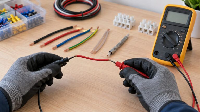
- Set the meter to ohms, or to continuity if the dial offers it. Plug the black lead into the common jack and the red lead into the resistance jack. The eCampusOntario chapter gives this lead order, and it says to start with the lowest setting on the ohms function.
- Touch the two probe tips together. The eCampusOntario chapter uses this check to confirm the leads, connections and battery, and it expects the display to show zero, or a very small value. Fluke says the same reading is ideal when the test leads touch.
- Hold the probes by their insulated parts, and touch the metal tips to the two ends of the bead. Fluke says to avoid touching the metal parts of the test leads, because the human body becomes a parallel resistance path. Make sure contact between the leads and the bead is good.
- Read the display and note the unit. The eCampusOntario chapter says to note whether the value is in ohms, kilohms or megohms before you record it.
- If the display shows OL, the meter sees no continuous path through the bead. This follows from the eCampusOntario description of OL on open leads. The sources do not give a rule for judging a bead from OL alone.
- Turn the meter off when you finish. Fluke lists this as a final step to prevent battery drain, and eCampusOntario says the same.
Reading the results
The sources give few numbers for bead readings, so this section states only what they say.
- A reading that stays near zero with the leads touching is the baseline. Fluke says relative mode subtracts test lead resistance, which it puts at typically 0.2 to 0.5 ohms.
- A two-lead reading includes the lead and contact resistance unless the meter subtracts them. Renesas says DC resistance should be measured with a “4-wire or Kelvin ohm meter,” which keeps the measuring leads out of the measured path. The sources we opened do not say whether a particular meter offers a four-wire ohms mode.
- A reading taken with the bead still on a board can differ from the bead’s own value. Fluke says the resistance of parallel components “usually” lowers the reading.
- Compare the reading with the datasheet for your exact part number, not with a value from memory. The sources we opened give no DC resistance for any bead, so this post cannot say what a normal reading is.
Common mistakes
- Testing the bead in circuit. Fluke says parallel components usually lower the reading, so the number you see may not be the bead’s own resistance.
- Testing with power on. eCampusOntario says to use an ohmmeter only on de-energized circuits.
- Leaving the meter on the ohms function. The eCampusOntario chapter says an ohmmeter should never be left on the ohms function when not in use.
- Skipping the lead check. The eCampusOntario chapter says the meter should be zero adjusted to start, which may need no more than touching the two probes together.
- Holding the metal tips. The body adds a parallel path, and Fluke says that lowers the total reading.
- Reading ohms as impedance. A DC reading is not the 100 MHz impedance that Renesas says datasheets normally specify.
How we chose
The scope is one bead, removed and out of its circuit, checked for continuity and DC resistance with a handheld multimeter. We kept only facts that a source we opened states in plain words, and each quoted line was checked against the fetched text of its page. We opened six sources on 2026-10-22: a Fluke resistance guide, a Fluke multimeter safety guide, an eCampusOntario chapter on resistance measurement, a Renesas application note on ferrite beads, and two OSHA pages. We did not use a retailer listing for any procedure or safety claim. Other pages were checked and left out. A NIOSH PDF and a TDK page returned error statuses, a Mouser copy of the Renesas note returned an access-denied page, and Murata and Würth datasheet links returned errors, a bot challenge or script-only pages with no text. An Analog Devices note could not be reached from curl during this session, so it is not cited. The part table in the Renesas note is not used as a rating source either, because a rating should come from the manufacturer’s datasheet, and that table is not one.
What we could not verify
The sources we opened do not give any of the following, so this post leaves them out.
- A DC resistance, rated current or impedance value for a named bead. The manufacturer datasheet pages checked for this post did not return readable text.
- The test current a multimeter uses in ohms mode, or whether that current affects a bead.
- Whether a bead’s DC resistance falls close to the typical lead resistance.
- Any impedance value at a frequency other than the one Renesas names.
- The resolution of any meter’s ohms range.
- Any CAT or voltage rating for a ferrite bead.
- Part-specific figures from the Renesas table, which lists DC resistance and current for named parts from several manufacturers. The table sits in an application note, not a manufacturer datasheet, so this post does not repeat its numbers.
The sources also do not explain how a bead’s impedance changes with temperature, age or board layout. Those points need the manufacturer’s datasheet, and this post does not make a claim about them.
Frequently asked questions
Can a multimeter confirm that a ferrite bead filters noise?
No. The Renesas note says impedance is normally specified at 100MHz, and an ohms reading gives a DC resistance value. A multimeter cannot show the impedance that a datasheet gives at that frequency.
Should I test a ferrite bead while it is still on the board?
Fluke says the best results come with the component removed, because parallel components can change the reading. Remove the bead or isolate it before you take the ohms reading.
What does an OL reading across a bead mean?
The eCampusOntario chapter says the meter reads over-limit resistance when the leads are left open. An OL reading across the bead therefore means the meter found no continuous path through it. The sources do not give a rule beyond that.
Is it safe to test a ferrite bead in a powered device?
No. eCampusOntario says to use an ohmmeter only on de-energized circuits, and OSHA’s interpretation requires live parts to be de-energized before work on or near them, unless that is infeasible. This post does not cover powered equipment.
Why does the datasheet method use a four-wire meter?
The Renesas note recommends a four-wire or Kelvin ohm meter for DC resistance. The note does not explain the method in detail, but Fluke’s relative mode shows why lead resistance matters: a standard reading includes it, at typically 0.2 to 0.5 ohms.
What value should a good bead read?
This post cannot say, because the sources we opened give no DC resistance for any bead. Find the DC resistance in the datasheet for your exact part number, and compare your reading with that figure after allowing for lead resistance.
Bottom line
With the bead out of the circuit and the circuit off, a multimeter can show continuity and a DC resistance reading. For filtering performance, use the impedance curve in the datasheet, because the meter does not measure it.
Sources
- Fluke, “How to Measure Resistance with a Digital Multimeter”: https://www.fluke.com/en-us/learn/blog/digital-multimeters/how-to-measure-resistance (opened 2026-10-22)
- eCampusOntario, “Introduction to Resistance Measurements,” Multimeters 101: https://ecampusontario.pressbooks.pub/multimeters101/chapter/1-6-introduction-to-resistance-measurements/ (opened 2026-10-22)
- Renesas, AN-805 “Recommended Ferrite Beads”: https://www.renesas.cn/zh/document/apn/805-recommended-ferrite-beads (opened 2026-10-22)
- Fluke, “Guide to digital multimeter safety”: https://fluke.com/en-us/learn/blog/safety/multimeter-guide (opened 2026-10-22)
- OSHA, 29 CFR 1910.333 Selection and use of work practices: https://www.osha.gov/laws-regs/regulations/standardnumber/1910/1910.333 (opened 2026-10-22)
- OSHA, standard interpretation dated 2006-07-28: https://www.osha.gov/laws-regs/standardinterpretations/2006-07-28 (opened 2026-10-22)