How to Test a Car MAP Sensor With a Multimeter
As an Amazon Associate we earn from qualifying purchases.
How to test a car MAP sensor with a multimeter starts with the ignition off and the battery negative cable disconnected, because the ground and wiring checks are resistance tests. Fluke describes a manifold absolute pressure (MAP) sensor as essential to fuel delivery and ignition timing, and says a faulty one can cause poor performance, rough idle, or trouble codes. This guide covers the ground and connector checks made with the ignition off, and the key-on voltage check for a voltage-type sensor. The sources we opened give no value for any specific sensor, so the final comparison has to use the manufacturer’s chart.
Quick answer
- Safety first: work on mains circuits can kill, so this guide covers only low-voltage car checks.
- With the ignition off and the battery negative cable disconnected, check the sensor’s ground for continuity. A steady beep near zero ohms means a good ground.
- With the ignition on and the engine off, Fluke expects about 4 to 5 V from a voltage-type sensor. Compare the reading with the manufacturer’s chart.
Electrical safety comes first
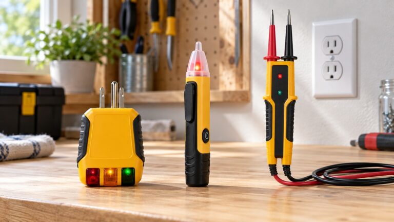
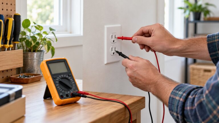
Work on mains circuits can kill. Before you measure anything, check that the meter’s CAT rating suits the circuit you are testing, and read the rating from the listing or the manufacturer’s manual. Panel and service work belongs to a licensed electrician.
Three opened sources support the first sentence. OSHA says its electrical standards are designed to protect workers from electric shock, electrocution, fires, and explosions. The UF/IFAS publication says electrical shock occurs when electrical current travels through the body to ground. Fluke says shock occurs when the human body becomes part of an electrical circuit.
The CAT rating is an overvoltage category, and it tells you which electrical environments a meter is built to handle. Tektronix describes CAT I as signal-level and electronics work, CAT II as local-level mains and appliances, CAT III as distribution-level mains and fixed installations, and CAT IV as the service drop to a building. Keysight’s manual for one multimeter describes CAT II as devices connected to mains at an outlet on a branch circuit. Fluke advises choosing a meter rated for the highest category you could potentially use it in, and says the ratings are usually located near the input jacks.
Voltage alone does not settle the question. Tektronix warns that a meter input designed for 600 volt CAT III may be internally limited and not suitable for 1000 volt CAT I or II use. It also says to observe the voltage and current limits shown on the meter or in its manual.
The UF/IFAS publication advises calling a licensed electrician when a breaker or fuse rating is unclear. None of the pages we opened covers licensing rules for homeowners, so this guide makes no claim about them. This guide gives steps only for the low-voltage circuits of a car, not for household wiring. UF/IFAS notes that shock concern is less for low-voltage 12-volt DC circuits, but it still advises disconnecting the power source before work on any electrical device.
This draft gives no steps for the engine control module, the intake system while the engine runs, airbag systems, or high-voltage hybrid and EV systems.
Battery safety comes before any step
Turn the ignition off and take the key or fob out of reach. KBB says ACC or ON without the engine running is not good enough. Parkers advises checking that the ignition is off and removing the key or fob, unless the owner’s manual says otherwise.
Disconnect the negative terminal first. KBB says this reduces the chance that a wrench touches both the battery terminal and the car’s body at the same time. Parkers warns that disconnecting the positive first could create a dangerous and powerful electric short. KBB describes the negative terminal as the one with a minus sign, often under a black cover.
Remove any metal jewelry first, since KBB says it can cause accidental short circuits. Keep tools off the battery. The Oregon DOT battery handout says never to lay tools on top of the battery, because they could touch both posts, or a post and ground, and create a short.
Hydrogen is a second hazard. The Oregon DOT handout says lead-acid batteries produce flammable hydrogen gas while being charged, and that a cigarette, tool, or spark from any source could ignite it. It also says the battery releases hydrogen while the car is running, not only when a charger is connected. The handout advises charging in a well ventilated area, and this guide gives no charging steps.
Polaris publishes the owner’s manual for an off-road vehicle, not a car. That manual warns that improperly connecting or disconnecting battery cables can result in an explosion, and says to disconnect the negative (black) cable first to reduce the chance of sparks. We cite it only for the cable order and the warning, not as a car maker’s procedure.
KBB says disconnecting a car battery carries risks, including electrical shock, short circuits, and damage to the vehicle’s electrical system. Parkers says disconnecting the battery can reset radio presets, the clock, and other electronic functions, so expect to set those again.
What you need before you start
- A digital multimeter with a DC volts setting and a resistance or continuity setting. For the voltage check, Fluke has the black lead in COM and the red lead in the voltage jack.
- A wrench for the battery clamps. KBB says a wrench set, socket set, or adjustable wrench is needed to loosen the bolts on the battery cables.
- The vehicle’s service manual or wiring diagram. Fluke tells readers to consult the wiring diagram to find the signal wire, and to consult the service manual for target values.
- A check of the sensor type. Fluke says most late-model MAP sensors give a variable DC voltage of about 0.5 V to 4.5 V, while some older units give a frequency signal. This guide covers the voltage type only.
Use back-probe pins where possible. Fluke says back-probing avoids damaging connector seals, and it says to make back-probe connections with the engine off.
Steps with the ignition off
Step 1: disconnect the battery. The Fluke continuity guide says to disconnect the battery negative terminal or ensure the circuit is not live before testing for continuity.
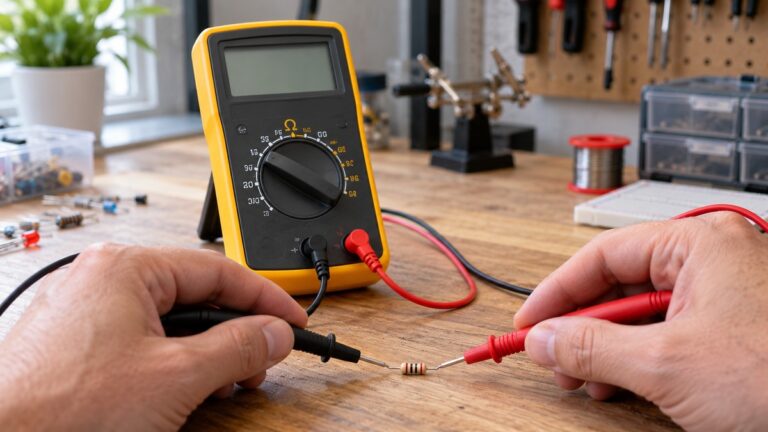
Step 2: set the meter. Fluke says to set the dial to Ω (resistance), then press the continuity button. It also warns to avoid testing powered circuits in continuity or resistance mode, because that can damage the meter.
Step 3: unplug the sensor. This is the scope of the ignition-off checks. The sources we opened do not describe how to release the connector latch on any vehicle, so use the service manual for that part of the job.
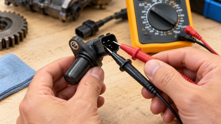
Step 4: check the ground. Fluke says to place one lead on a bare engine block or chassis ground, and the other on a component ground terminal or wire. In this check, the other lead goes on the ground terminal in the sensor’s connector. Fluke says a steady beep with a reading near 0.0 to 0.2 ohm indicates good continuity.
Step 5: read a failure. If there is no continuity, Fluke says to suspect a broken ground strap or a corroded terminal. A reading with no beep and an open-loop or high reading means an open circuit, corrosion, or a bad connection.
Step 6: check the harness end to end. Fluke describes an end-to-end check on a wire harness, with a steady beep and a near-zero reading when the path is good. If the other end of the signal wire sits at the engine control module, this guide gives no step for that end, because it is outside the scope of this draft.
Ignition-on voltage check
Step 7: reconnect. KBB says to reconnect the positive terminal first, then the negative. Reconnect the sensor, because the Fluke voltage check back-probes the connected signal wire.
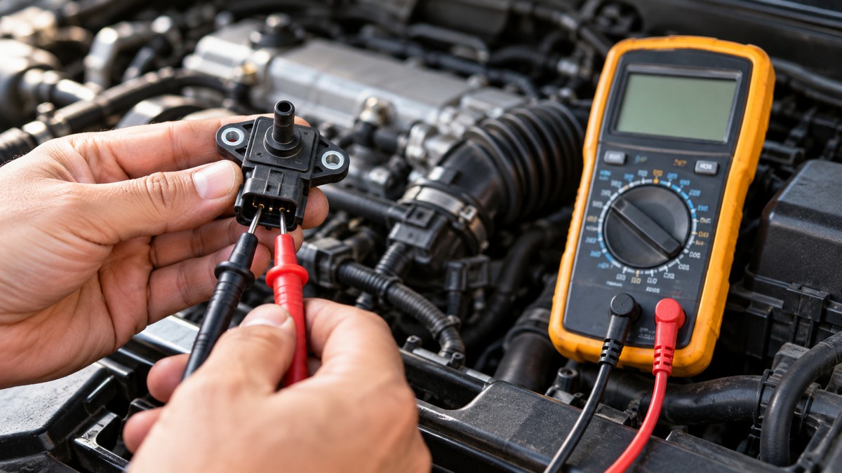
Step 8: set up the voltage check. Fluke says to turn the ignition on without starting the engine, which it calls KOEO. Set the meter to DC volts. Back-probe the signal wire with the red lead, and attach the black lead to a reliable chassis or battery ground.
Step 9: read the output. For a voltage-type sensor, Fluke expects about 4 to 5 V, and says the reading is high because manifold pressure equals barometric pressure. Fluke gives 0.5 to 4.5 V as the usual output range for late-model sensors. These readings, Fluke says, confirm the sensor has power and ground.
Step 10: check the reference. Fluke describes a typical three-wire MAP connector with a 5 V reference, a ground, and a signal wire. It says a flat or stuck signal often indicates no 5 V reference or a poor ground. The sources we opened give no separate reference reading, so this guide gives none.
The Fluke article also describes a vacuum check with a hand pump. Its example table is labeled typical, not a specification, and the article gives different figures for the same vacuum level. This guide leaves that check out.
Reading the results
- Ground. A steady beep with a near-zero reading means the ground path is good. No beep, or a high reading, points to a break, corrosion, or a bad connection, according to Fluke.
- Key-on signal. A voltage-type sensor reading about 4 to 5 V with the ignition on and the engine off matches the Fluke baseline. Fluke presents that baseline as confirmation of power and ground.
- Flat or stuck signal. Fluke says to verify power and ground first, because a flat or stuck signal often means no 5 V reference or a poor ground.
- Outside the chart. Fluke says to refer to the manufacturer’s chart for the specified values. The sources we opened do not say that a reading outside 4 to 5 V is a fault.
Common mistakes
- Testing a powered circuit in resistance mode. Fluke warns this can damage the meter.
- Skipping the battery disconnect. Fluke says to disconnect battery power or isolate the circuit before continuity testing.
- Piercing the wire. Fluke says back-probing is preferred to avoid damage to insulation and seals.
- Reconnecting the negative first. KBB gives the order as positive first, then negative.
- Confusing continuity with voltage. Fluke says continuity means low resistance, not necessarily that voltage is present.
- Blaming the sensor for a flat signal. Fluke says a flat or stuck signal often points to the reference or the ground first.
- Ignoring the key fob. Parkers says disconnecting the battery can lock the fob in place on some cars.
- Assuming a pin order. The sources we opened give no pin order for any vehicle. Check the wiring diagram before you touch a pin.
Frequently asked questions
Can I check the ground with the ignition off?
Yes. Fluke’s continuity method is a resistance test, and it says to disconnect the battery negative terminal or make sure the circuit is not live first.
What voltage should a voltage-type MAP sensor show with the key on?
Fluke gives about 4 to 5 volts for a voltage-type sensor with the ignition on and the engine off. The same article gives 0.5 to 4.5 volts as the usual output range for late-model sensors. The sources we opened give no value for a specific sensor, so use the manufacturer’s chart.
What does the continuity beep mean?
Fluke says a beep with a low reading means good continuity. A steady beep with a reading near 0.0 to 0.2 ohm is the clearest sign. No beep with an open-loop or high reading points to an open circuit or a bad connection.
Why does a voltage-type sensor read high with the key on?
Fluke says manifold pressure equals barometric pressure with the engine off, so the reading is high. Fluke presents that baseline as confirmation that the sensor has power and ground.
Can I pierce the wire to reach the signal?
Fluke recommends back-probing where possible, because piercing can damage the wire insulation and connector seals.
Does this guide cover the vacuum test?
No. Fluke describes a hand-pump vacuum check, but its example table is labeled typical and the article gives two different figures at the same vacuum level. See the section on what we could not verify.
How we chose
We chose sources that give a procedure, a meter behavior, a CAT rating, or a safety statement, and that we could open with curl on 2026-10-22. Manufacturer pages came first: Fluke for MAP testing and continuity, Tektronix and Keysight for CAT ratings, and Polaris for a cable order in an off-road vehicle manual. Government and university pages covered the hazards: the Oregon DOT handout and OSHA for battery and electrical hazards, and the UF/IFAS publication for shock and the licensed electrician point. KBB and Parkers are consumer sites, and they appear only for the battery disconnect order. A step appears in this guide only when an opened source gives it, and each quoted sentence was matched against the fetched page text. Pages that returned 403 or 404 are not used.
What we could not verify
- Vehicle service information. The sources we opened include no car maker’s service information, so this guide gives no supply, ground, or signal pin order, no connector view, and no resistance value for any MAP sensor.
- Sensor specifications. No opened source gives a key-on or vacuum value for a specific MAP sensor. Fluke gives typical ranges only.
- The vacuum example. Its typical table gives 1.5 V at 20 inHg, and one sentence gives about 1 V at the same level. Its altitude notes also disagree with each other, so this guide uses neither.
- The continuity threshold. One Fluke guide puts the beep at about 25 to 50 ohms, and another says below about 30 ohms. The near-zero reading is the clearer guide.
- Age of the CAT wording. The Tektronix text refers to standards expected in 1997, so its wording is dated. The Keysight wording applies to that one meter.
- The phrase “can kill.” None of the opened pages uses those words. The sentence rests on the shock and electrocution wording above.
- Homeowner licensing. None of the opened pages covers licensing rules for homeowners.
- Battery procedures from car makers. Polaris covers an off-road vehicle, and no car maker’s battery procedure was opened. KBB and Parkers are consumer sites.
Bottom line
Disconnect the battery, check the ground with the ignition off, and compare the key-on output with the manufacturer’s chart before you judge the sensor.
For the continuity steps, see our guide on how to use a continuity tester. For car voltage meters, see our roundup of digital voltage meters for cars. For the CAT rating background, see our 600 V CAT III explainer.
Sources
- https://www.fluke.com/en/learn/blog/digital-multimeters/how-to-test-map-or-bp-map-sensors-with-a-multimeter (opened 2026-10-22)
- https://www.fluke.com/en/learn/blog/digital-multimeters/how-to-perform-automotive-continuity-checks-with-a-multimeter (opened 2026-10-22)
- https://www.fluke.com/en/learn/blog/digital-multimeters/common-automotive-testing-with-a-multimeter (opened 2026-10-22)
- https://www.fluke.com/en/learn/blog/safety/multimeter-guide (opened 2026-10-22)
- https://www.kbb.com/car-advice/disconnect-car-battery (opened 2026-10-22)
- https://parkers.co.uk/car-advice/how-to-disconnect-your-car-battery (opened 2026-10-22)
- https://publications.polaris.com/owner/owners-manuals/0000867965.xml/$/0000603377 (opened 2026-10-22)
- https://www.oregon.gov/odot/Programs/T2/TailgateTalks/BatteryCharging.PDF (opened 2026-10-22)
- https://www.osha.gov/electrical (opened 2026-10-22)
- https://ask.ifas.ufl.edu/publication/EP571?downloadOpen=true (opened 2026-10-22)
- https://www.tek.com/en/documents/whitepaper/understanding-handheld-dmm-specifications (opened 2026-10-22)
- https://www.keysight.com/ph/en/assets/9925-01336/user-manuals/DM34460-Series-DMM-Users-Guide.pdf (opened 2026-10-22)