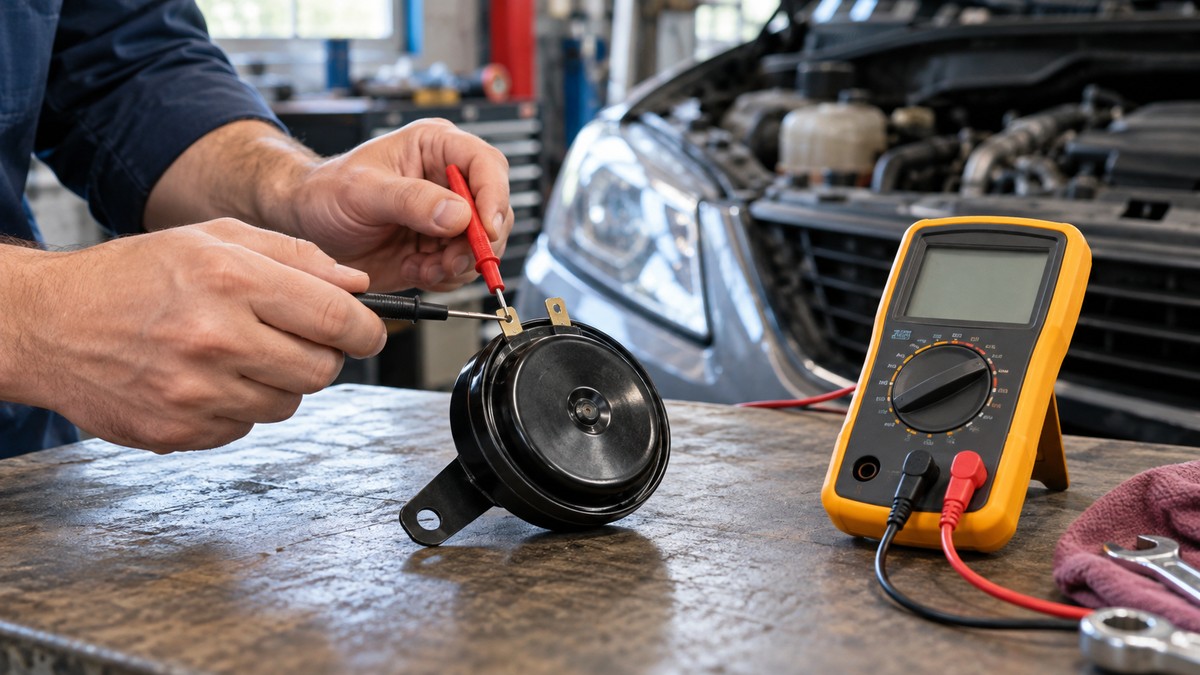
How to Test a Car Horn With a Multimeter
As an Amazon Associate we earn from qualifying purchases.
How to test a car horn with a multimeter comes down to three checks: the horn’s own resistance with its wires disconnected, the ground path, and the voltage that reaches the horn while the horn button is pressed. Disconnect the negative battery cable before any resistance check. The method below follows a Stellantis dealer bulletin on horn complaints and Fluke’s multimeter guidance. That bulletin covers only some models, so confirm each terminal against your vehicle’s wiring diagram before you probe it.
Quick answer
- Safety first: work only on the 12-volt horn circuit, and disconnect the negative battery cable before any resistance check.
- Test the horn’s resistance with its wires disconnected, never on a powered circuit.
- Read the voltage at the horn with the ignition on and an assistant pressing the horn button.
Electrical safety first
Work on mains circuits can kill. Before you measure anything, check that the meter’s CAT rating suits the circuit you are testing, and read the rating from the listing or the manufacturer’s manual. Panel and service work belongs to a licensed electrician.
A car horn runs on 12 volts from the battery, not on mains, so the steps below stay on low-voltage vehicle work. OSHA says “Fatal electrocution is the main risk, but burns and falls are also hazards” in its guide to working safely with electricity. Its general industry rule also says live parts “shall be deenergized before the employee works on or near them,” and that only qualified persons may work on parts that stay energized. OSHA’s electrical safety toolbox talk adds, “Electrical work should only be assigned to qualified employees.”
CAT ratings describe the part of the electrical system a meter is built for. Fluke’s supplement says Measurement Category II applies to circuits “connected directly to utilization points,” such as socket outlets. Category III covers the distribution part of a building’s mains. Fluke’s IEC category page warns that a rating which does not match the task “can actually explode if used improperly.” None of the sources we opened says a particular meter is safe for household mains, so this guide does not treat any meter as safe for that use.
This guide does not cover airbag systems, steering-wheel clockspring work, or high-voltage hybrid and EV systems, and it gives no steps for them.
Battery safety before you start
The Kia owner’s manual says, “The battery produces hydrogen gas which may explode if exposed to flame or sparks,” and “Automobile batteries contain sulfuric acid.” Its jump-start instructions also tell you to “wear protective glasses.” Fluke makes the same warning for lead-acid batteries: “they can emit explosive gas and contain acid.”
OSHA’s battery charging rules are written for powered industrial trucks, not for a passenger car. They still show the same hazard. The rule requires “adequate ventilation for dispersal of fumes from gassing batteries,” and says “Precautions shall be taken to prevent open flames, sparks, or electric arcs in battery charging areas.” Our own reading of those two rules for a car test is simple: keep flames and sparks away from the battery, and work where fumes can clear.
Disconnect the negative battery cable first and reconnect it last. Fluke’s continuity guide says to “Disconnect the battery negative terminal or ensure the circuit is not live” before a continuity check. The Stellantis bulletin says that if trouble codes do not resolve a horn complaint, you should “disconnect the negative battery cable, wait two minutes for capacitor discharge” before more diagnosis. A Polaris owner’s manual gives the same order: “When removing the battery, always disconnect the negative (black) cable first.” That is a powersports manual, not a passenger-car source, so use it only as a general check of the order.
Before you connect the leads, inspect the terminals. Fluke’s battery guide says to “Always inspect battery terminals for corrosion or looseness before testing.”
Preparation
Fluke’s battery guide says to “Set the dial to VDC (DC volts)” and to use “Red lead in V/Ω, black lead in COM.” The horn circuit is a 12-volt DC circuit from the battery, so the DC setting applies here (our own assumption based on the battery voltage). The Fluke guide describes this setting for battery voltage, not for a horn connector, so confirm the setting in your meter’s manual.
Read the CAT rating from your own meter’s listing or manual before you connect the leads. Fluke’s 88V product page lists “CAT III 1000 V” and “CAT IV 600 V.” That is one model’s listing, and this guide does not recommend that meter. For a wider look at meters, see our multimeter buying guide.
Check the battery condition before you blame the horn. The bulletin notes that “Horn tones weaken when the battery voltage is low.” A weak battery can make a good horn sound poor, so note the battery’s state first. For a battery check that starts from resting voltage, see our guide to car battery checks with a multimeter.
Probe with care. The bulletin names a Stellantis test lead kit: “Use Test Lead Kit 2064100081” for probing. It also says to “never face or back probe terminals to avoid pin damage.” The sources we opened give no substitute kit, so use leads that the bulletin’s method allows, and never push a probe in from the face or back of a terminal.
Steps
Step 1: Disconnect the battery and check the horn fuse
Turn the ignition off. The bulletin says to record any trouble codes and perform code diagnostics first. If that does not resolve the fault, disconnect the negative battery cable and wait two minutes before you go on. The bulletin gives the wait “for capacitor discharge,” but it does not say which capacitor it means.
Next, check the horn fuse. The bulletin says to “Verify that the 20A fuse in the Power Distribution Center (PDC) is not open and its installation is correct (fully inserted and making connection).” It lists fuse numbers by model code: F40 or F57 for DT, F42 for DJ, D2, DD and DP, F91 for JL and JT, and F66 for WS. Fluke’s continuity guide notes that for “a removed component (like a fuse),” power disconnection is not required, so a fuse can be tested once it is out of the car.
Step 2: Disconnect the horn and measure its resistance
Disconnect the horn’s wires at the horn so that the horn is out of the circuit. Set the meter to ohms or continuity. Fluke says to “Disconnect battery power or isolate the circuit before testing for continuity,” and warns to “Avoid testing powered circuits in continuity or resistance mode.” Touch the two leads to the two horn terminals.
A beep means the meter reads continuity. Fluke’s continuity guide puts a beep at “resistance below ~25–50 ohms,” while its 11-test article says a beep is “typically below about 30” ohms. If the meter reads OL or a very high value, Fluke’s continuity guide describes that as an “Open circuit or very high resistance,” which suggests a break, corrosion, or a bad connection.
The sources we opened do not give an ohm value for a horn winding. Compare the reading with the vehicle’s service information, and treat the beep threshold as a continuity check, not a horn specification. The bulletin describes dual horns, so on a car with two horns, test each one.
Step 3: Check the ground path
With the battery still disconnected, check the horn’s ground. Fluke’s ground check says to “Place one lead on bare engine block or chassis ground” and to place the other lead on the component’s ground terminal or wire. If there is no continuity, Fluke says to “suspect a broken ground strap or a corroded terminal.”
Step 4: Inspect the harness connector
Look at the connector before you blame the horn. The bulletin lists conditions to check: “Check for damaged connector locks, corrosion, or signs of water intrusion,” “Bent terminals,” and “Overheating due to poor connection (terminal discolored).” It also mentions “Terminals pushed into the connector cavity.” The bulletin names a terminal drag test, but the sources we opened do not describe it in steps, so this guide does not describe it either.
Step 5: Reconnect the battery and check the voltage at the horn
Reconnect the negative battery cable, then turn the ignition on. The bulletin’s voltage check is to have an assistant press the horn button while you “use a Digital Volt-Ohm Meter to measure voltage, from the PDC relay output to the horn.” The bulletin also says to check ground at the relay coil harness connectors. It does not say which meter lead goes to which point, so use the wiring diagram to decide. Keep your hands clear of fan belts or moving parts, as Fluke’s battery guide advises.
Use DC volts, and read the meter while the horn button is held. The bulletin’s branch logic follows below.
Reading the results
The bulletin gives a horn operating range of “between 9.3V and 16V, ideally at 13V,” with a maximum draw of “6 amps (single horn) or 12 amps (dual horns).” The 2024 version of the bulletin says the same thing in other words: “Horns are designed to work between 9.3v and 16v.” Treat these as the figures for the models the bulletin covers, not as a general rule for every car.
The bulletin’s voltage branches read as follows. If the answer to “Is voltage present?” is yes, the bulletin says to “Check and repair the circuit for a voltage short.” If the answer is no, it says to “Check the PDC harness for open circuit or connection issues.” For ground, a yes answer to “Is there continuity to ground?” leads to “Check and repair the circuit for ground short,” and a no answer leads to “Check the BCM harness connections for issues.” The sources we opened do not explain why each answer points to each fault, so read the branches against your wiring diagram before you act on them.
For the resistance check, a beep with a low reading means continuity, and no beep with an OL or high reading means an open or very high-resistance path. Neither result gives a horn value, so the resistance check shows whether the winding is open, not whether it matches the specification.
Common mistakes
- Taking resistance readings with the battery connected. Fluke says that testing powered circuits in resistance mode “can damage the meter.”
- Assuming continuity means voltage. Fluke’s continuity guide says “continuity means low resistance, not necessarily that voltage is present.”
- Probing the connector from the face or back. The bulletin says never to do this, to avoid pin damage.
- Blaming the horn during a low battery. The bulletin says horn tones weaken when battery voltage is low.
- Skipping the wait after disconnecting the battery. The bulletin calls for two minutes before more diagnosis.
Frequently asked questions
Do I need to disconnect the battery to test a horn?
For resistance checks, yes. Fluke’s continuity guide says to isolate the circuit or remove battery power first, and the Stellantis bulletin puts the negative cable first once trouble-code checks do not explain the fault.
What resistance should a horn read?
The sources we opened do not give one. Fluke’s continuity guide puts a beep at roughly 25 to 50 ohms, and its 11-test article uses about 30 ohms, so the two thresholds differ. Use a beep only as a continuity check.
What voltage should reach a horn?
For the models the bulletin covers, the range is 9.3 V to 16 V, with about 13 V as the ideal. Those figures come from one manufacturer’s bulletin, so check your own service information before you accept a reading.
Why does my horn sound weak?
The bulletin lists a weak, off-tone, or inoperative horn as the symptom it covers. Low battery voltage makes horn tones weaker, and poor connections can also cause trouble, so the bulletin lists corrosion and overheated terminals among the connector conditions to check.
Can I test the horn switch on the steering wheel?
No. This guide gives no steps for the steering-wheel switch or for any part behind the steering wheel.
Is my meter safe for household mains?
No meter is presented here as safe for household mains. Read the CAT rating from your own meter’s listing or manual. The sources we opened give CAT ratings only for specific Fluke models.
How we chose
We wanted steps that a manufacturer, a meter maker, or a public agency describes in plain words, and that we could open and quote. Each step in this guide has at least one source behind it, and the battery and electrical safety statements rest on two or more. Retailer pages and forum posts were not used for any step. For car-specific meter picks, see our digital voltage meter picks for cars.
We opened 23 pages with curl on 2026-10-21. Fourteen support statements in this guide. Five returned 403 or 404 and were not used: an OSHA electrical hazards page, a NIOSH electrical PDF, a 1962 Buick chassis manual page, a Kia manual page, and a university learning page. Four were opened but not used: an eCFR page that returned a bot-check screen, an OSHA meatpacking guide, a NIST page, and an earlier May 2024 Stellantis bulletin for the same case number.
What we could not verify
The sources we opened do not give an ohm value for a horn winding, so this guide does not give one. They do not state a CAT rating for the meter you own, and they do not say any meter is safe for household mains. The bulletin covers only the model codes it names, and its fuse numbers apply to those codes alone. It does not say which meter lead goes to which point in the relay-to-horn voltage check, or which capacitor the two-minute wait refers to. Fluke’s two articles give different beep thresholds. The Fluke IEC page cites the 2012 edition of NFPA 70E, and the sources we opened do not cover the current edition. The sources we opened say electrical work belongs to qualified people, but they do not address licensing, so the licensed-electrician line in the safety section follows the site’s own policy.
Sources
- Fluke, automotive continuity checks: https://www.fluke.com/en-au/learn/blog/digital-multimeters/how-to-perform-automotive-continuity-checks-with-a-multimeter
- Fluke, common automotive testing: https://www.fluke.com/en-ie/learn/blog/digital-multimeters/common-automotive-testing-with-a-multimeter
- Fluke, how to measure battery voltage: https://www.fluke.com/en-us/learn/blog/digital-multimeters/how-to-test-a-battery-with-a-multimeter
- Fluke 88V product page: https://www.fluke.com/en-us/product/electrical-testing/digital-multimeters/fluke-88v
- Fluke 88 V users manual supplement: https://media.fluke.com/c3265e25-e2a4-4ab7-8e53-b10800c2bd24_original%20file.pdf
- Fluke, IEC category ratings: https://www.fluke.com/en-us/learn/blog/safety/iec-category-ratings-use-the-right-tools-for-the-job
- Stellantis technical service bulletin, horn system, rev. C (March 2025): https://static.nhtsa.gov/odi/tsbs/2025/MC-11015602-0001.pdf
- Stellantis technical service bulletin, horn system, rev. B (September 2024): https://static.nhtsa.gov/odi/tsbs/2024/MC-11007172-0001.pdf
- Kia owner’s manual, jump-starting: https://ownersmanual.kia.com/full_webhelp/MV1/2024/en_RG/topics/idEmpty00667.html
- Polaris owner’s manual, battery removal: https://publications.polaris.com/owner/owners-manuals/0000715917.xml/$/0000730121
- OSHA 29 CFR 1910.178, powered industrial trucks: https://www.osha.gov/laws-regs/regulations/standardnumber/1910/1910.178
- OSHA 29 CFR 1910.333, selection and use of work practices: https://www.osha.gov/laws-regs/regulations/standardnumber/1910/1910.333
- OSHA, Working Safely with Electricity (OSHA 3942): https://www.osha.gov/sites/default/files/publications/OSHA3942.pdf
- OSHA, Electrical Safety Toolbox Talk (OSHA 4496): https://www.osha.gov/sites/default/files/publications/OSHA4496.pdf