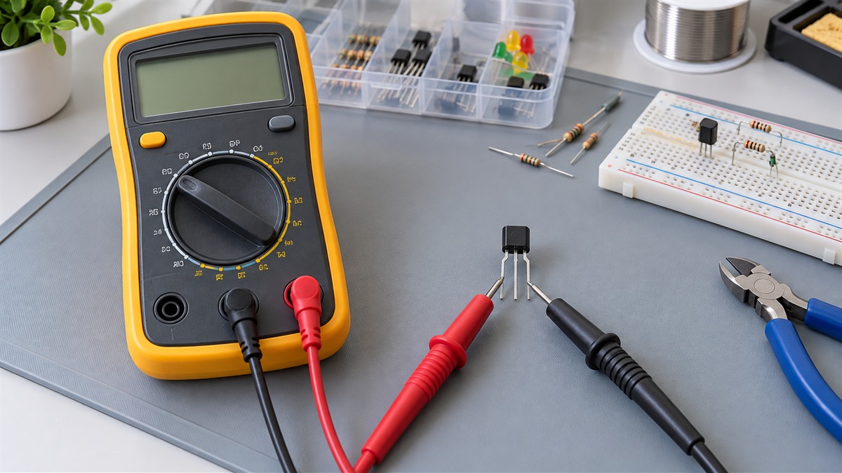
NPN Transistor Test
As an Amazon Associate we earn from qualifying purchases. Details
You can check an NPN transistor with an ordinary multimeter by treating its two internal junctions as diodes. Set the meter to its diode setting, touch the probes to the three leads in turn, and note which pairs conduct. This guide follows the method taught in university electronics labs, explains what each reading means, and says plainly what the test cannot tell you. It is a quick screen for a dead or shorted part, not a measurement of gain or switching speed. Read your meter manual for the exact symbol and probe jacks.
Quick answer
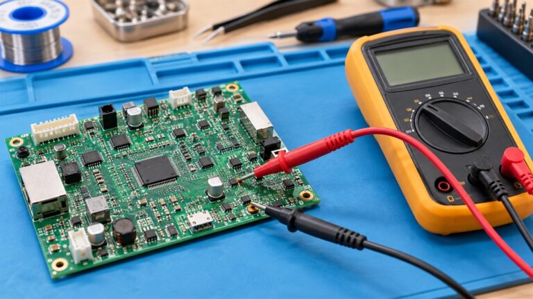
Put the meter on the diode setting. Put the red probe on the base and the black probe on the emitter, then on the collector. On a good NPN part both of those pairs conduct. Swap the probes and they should not. Then probe between collector and emitter in both directions, and expect no conduction. If all three checks pass, the transistor is almost always fine, which is how a University of Utah lab handout puts it.
What the test is based on
A bipolar junction transistor, or BJT, consists of two pn junctions that each act like a diode. The Utah lab states that these diodes can be tested just like any other diode, with most multimeters. It calls the result a quick-and-dirty way to test a transistor and a good way to learn about an unknown part.
The diode setting matters. The same lab notes that most multimeters do not use enough voltage in the regular ohmmeter setting to forward bias a diode. Without the special setting the meter may show little or no conduction in either direction. Look for the diode symbol on the dial.
Before you start
- A multimeter with a diode setting. If you are still choosing one, our best multimeter and auto-ranging digital multimeter guides compare the common options.
- The datasheet. Leads differ between parts. For the 2N3904 used in an Auburn University lab, the leads read emitter, base, collector from left to right when you look at the flat side. Do not assume that order for another part.
- The part out of circuit and the board de-energized. The Utah lab tests a loose transistor. See the safety note below.
Step by step
- Mark the three leads 1, 2 and 3 on a sketch, and make a small table of six probe combinations.
- Set the meter to the diode setting.
- Measure all six ways, red then black, and record each reading.
- Find the two combinations that conduct. The lead common to both is the base.
- If the base is the red (positive) probe in both cases, the part is an NPN. If the base is the black (negative) probe in both cases, it is a PNP.
- The Utah lab adds that the lowest reading often belongs to the base-collector junction, which hints at which outer lead is the collector. Check that against the datasheet instead of trusting it.
- Check collector to emitter in both directions. There should be no conduction.
How to read the results
| What you see | What it suggests |
|---|---|
| Base to emitter and base to collector conduct with red on the base, and nothing conducts when the probes are swapped | A working NPN pair of junctions |
| The same, but with black on the base | A PNP part, not an NPN |
| Collector to emitter conducts in either direction | Not behaving like a normal transistor, so suspect a short |
| A junction that does not conduct in either direction | Not behaving like a diode, so suspect an open junction |
| Little or no conduction on the ohmmeter setting | The meter may not supply enough voltage. Switch to the diode setting |
What this test does not tell you
The diode check says the two junctions behave. It does not measure current gain, often written beta or hFE, and it does not show how the part performs in a circuit. The Utah lab treats the multimeter check as Experiment 1 and goes on to measure beta against collector current in Experiment 2. For gain or a full transistor curve you need a tester or a bench setup, not just the diode setting.
Worked example: the numbers behind a 2N3904 check
Worked example. The Utah handout uses a 2N3904 in a small circuit with an 8 V supply and a 3 V base supply. It assumes a base-emitter drop of 0.7 V, so the emitter sits near 2.3 V. To set an emitter current of 3 mA, written as 0.003 amps, the emitter resistor is 2.3 V divided by 0.003 amps, about 767 ohms, and the lab says to use the closest value in the parts kit. For a 30 mA target, written as 0.03 amps, the same arithmetic gives about 77 ohms. The Auburn page lists the 2N3904 limits as 0.2 amps maximum working current and 0.625 watts maximum power dissipation. These figures show why a part that passes the diode check can still fail in a circuit that exceeds its ratings.
Ohmmeter-only method
A Wright State University lab handout shows a way to find the base and the NPN or PNP type with only the ohmmeter function. It starts by measuring a 1N4148 reference diode in both directions, notes that the red lead from the meter’s positive input is the more positive one, and then compares the transistor’s junction readings with the diode’s. Use this only if your meter has no diode setting.
Safety note
The U.S. Occupational Safety and Health Administration states in 29 CFR 1910.333(a)(1) that live parts to which an employee may be exposed shall be deenergized before the employee works on or near them, with exceptions where deenergizing adds hazards or is infeasible. Under (b)(2)(iv)(B), a qualified person must use test equipment to verify that circuit elements and equipment parts are deenergized. The rule covers workplaces, but the same order applies at a bench: power down and confirm before you touch a board.
Related guides
- Checking another part with the same meter: capacitor tester guide.
- Confirming a wire or lead is unbroken: continuity test with a voltmeter.
Frequently asked questions
How do I tell an NPN from a PNP with a multimeter? In diode mode, find the base: the lead common to the two conducting pairs. If the base is the red probe in both, it is an NPN. If it is the black probe in both, it is a PNP.
Can I test a transistor while it is soldered on a board? The lab tests use a loose part. On a board, other components can add paths that change the readings, so lift a lead or remove the part when you can.
Does a passing diode test mean the transistor is good? Almost always for a gross fault, according to the Utah lab, but it does not measure gain or ratings.
Why does my meter show nothing on the ohmmeter setting? Most meters do not apply enough voltage there to forward bias a junction. Use the diode symbol on the dial.
Which lead is the collector? Check the datasheet. The lowest reading often marks the base-collector junction, but treat that only as a hint.
Sources
- University of Utah, ECE 2100 BJT Intro lab: the diode-setting transistor test, base identification and NPN versus PNP
- Wright State University, BME 3512 Lab 4: finding the base and type with the ohmmeter function and a 1N4148 reference
- Auburn University, ELEC 2210 BJT page: 2N3904 lead order and ratings
- OSHA: 29 CFR 1910.333: deenergize live parts and verify with test equipment