How to Test a Car Ground Connection With a Multimeter
As an Amazon Associate we earn from qualifying purchases.
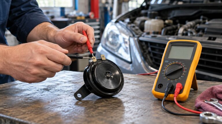
How to test a car ground connection with a multimeter comes down to measuring the voltage drop across the connection while the circuit is switched on and carrying current. A resistance reading taken with the battery disconnected can confirm an open or badly corroded path, but a ground can pass that check and still drop too much voltage under load. Work along the ground path in small sections, compare each reading with the limit in your car’s service information, and repair the connection that reads high before you replace any part.
Electrical safety
Work on mains circuits can kill. This guide does not cover household wiring, wall outlets, panels, breakers or service wiring. Panel and service work belongs to a licensed electrician.
Meter ratings still matter on a car. The Fluke 88V manual we opened says: “Use caution when working with voltages above 30 V ac, 42 V ac peak, or 60 V dc. These voltages pose a shock hazard.” Read the CAT rating and voltage rating from the listing or the manual for your own meter. If the listing or manual does not state a CAT rating, do not assume one.
Disconnect the battery before any resistance check. Fluke’s continuity guide says to “Disconnect battery power or isolate the circuit before testing for continuity,” and warns against “testing powered circuits in continuity or resistance mode” because this can damage the meter. The Drive warns that careless testing can cause “electrical shock, and potential fires.”
The voltage drop test is the exception, because it needs the circuit on. Before you crank the engine or switch on a load, follow the service information for disarming the ignition or the fuel system. Fluke’s starter guide also says to keep “hands and leads clear of moving parts.”
Keep high-voltage and airbag systems out of scope. The ASE standard we opened says electrified propulsion vehicles “have high-voltage DC and AC systems” that “can cause personal injury, severe burns, electric shock, and even fatal injury.” The Fluke 88V manual tells users to “Follow the manufacturers test procedures when testing air bags.” Do not probe airbag circuits or the high-voltage cables of a hybrid or electric car with this method.
Quick answer
- For a loaded test, put the red lead on the battery negative post, put the black lead on a bare-metal ground point, switch on the circuit, and read the DC volts.
- For a resistance check, disconnect the battery, set the meter to ohms or continuity, and read between the ground point and the chassis or engine block.
- Fluke’s application note says a ground-side restriction is the only thing that causes readings greater than 0 to 0.1 V in a ground circuit, so a small reading is worth tracing.
- The sources disagree on the pass limit. The ground-side limits in the sources we opened sit between 0.1 V and 0.5 V, depending on the test and the circuit.
How a ground connection carries current
A ground connection completes the return path for every load on the car. Fluke’s application note explains that “voltage falls to about zero on the ground side, but current keeps flowing toward the battery.” Because the voltage in a healthy ground circuit should be about zero, a ground that reads well above zero while the circuit is loaded is restricted, even if the wire looks sound.
Fluke’s automotive blog says “Rust, grease, vibration, and/or careless repairs often restrict the circuit from the engine/body back to the battery.” It also notes that “many components, such as engine sensors, share a common ground,” so one bad ground can affect several systems at once.
Before you start
Get the procedure for your own car first. The Fluke 88V manual says to “Consult your service manual for test procedures specific to your car.” The AutoDTCs guide also recommends a wiring diagram that shows the ground point locations for the specific vehicle.
- Set the rotary switch to DC volts for voltage drop, as Fluke’s starter guide does.
- Use an auto-ranging meter if you have one. Gears Magazine says the auto-range feature “saves you the guesswork.” Without auto-ranging, Fluke says to use a low-voltage (0-1 V) scale for voltage drop testing.
- Probe bare metal. Fluke’s starter guide says “Probe on bare metal; paint or corrosion skews results,” so scrape paint or corrosion away from each contact point.
- For low-current circuits such as computer grounds, use a high-impedance meter. Fluke warns that a low-impedance voltmeter may load a low-current circuit “so much that it gives an incorrect reading or no reading whatsoever.”
Method 1: Loaded voltage drop test on the ground side
This test finds a ground that passes a resistance check but drops voltage under current. Fluke’s application note sets the rule: “Unless you operate the circuit so current flows through it, you can’t measure voltage drop.” The NHTSA-posted technical tip gives the same instruction in short form: “Operate or turn ON the circuit.”
- Set the meter to DC volts, with auto-range or the lowest range that covers the expected drop.
- Put the red lead on the battery negative post. AutoDTCs says to make “metal-to-metal contact with the post itself, not the cable clamp.”
- Put the black lead on a clean, bare-metal spot on the engine block, the chassis, or the component ground. AutoDTCs says to scrape any paint or corrosion away first.
- Turn on the load. AutoDTCs gives an accessory example of high beams, the rear window demister, the blower on maximum speed and the air conditioning, with the engine off and the battery fully charged. For a starter ground, Gears Magazine has you crank the engine for approximately five seconds.
- Read the DC volts while the load runs, and write the reading down with the point you tested.
- Move the black lead to the next ground point, such as the firewall, a chassis rail or a body junction block, and read again. AutoDTCs says “A point that reads significantly higher than others on the same chassis has a fault between it and the battery negative terminal.”
- Repair the fault, then repeat the test under the same load. AutoDTCs warns that “the same load that revealed the fault must be reapplied after the repair.”
If a reading is high, find the section that causes it. Keep one lead on the battery negative post and move the other lead back along the ground path, one section at a time. Gears Magazine says “When the voltage drop measures normal again, you have reached a healthy section of the circuit.” Autotechnician describes the same method, moving the probe back toward the battery ground until the meter reads zero. The high resistance sits between the last high reading and the first normal reading.
Method 2: Resistance check with the battery disconnected
A resistance check is quick, and it can catch a broken or badly corroded ground. Fluke’s continuity guide gives these steps:
- Disconnect the battery negative terminal, or make sure the circuit is not live.
- Set the dial to Ω (resistance), then press the continuity button.
- Zero the leads. The Fluke 88V manual says test leads add error to resistance readings. Touch the probe tips together and use the relative (REL) mode, which subtracts the value automatically.
- Place one lead on bare engine block or chassis ground, and the other on the component ground terminal or wire.
- Read the meter. Fluke says “A steady beep with a near-zero reading (~0.0–0.2 Ω) indicates good continuity.” If there is no continuity, Fluke says to “suspect a broken ground strap or a corroded terminal.”
Two limits apply. The Fluke 88V manual explains that “the resistance reading represents the total resistance of all paths between the probes.” AutoDTCs makes the bigger point: a ground that “passes a continuity check and shows near-zero resistance on a multimeter can still drop enough voltage under real operating current.” For an engine-to-chassis strap, The Car Resource says “a good strap shows less than 0.1 Ω.” A resistance result alone does not clear a ground, so confirm it with Method 1.
If you are new to continuity mode, read our guide to using a continuity tester before you run these steps.
Reading the results
The sources do not agree on one pass limit. The table gives each figure with the test it belongs to.
| Source | What was measured | Limit the source gives |
|---|---|---|
| Fluke application note | Ground side, circuit loaded | “0.10 V at a ground” when no manual value is listed; “recommended working limit is 0.10 V-drop across low-current wires and switches” |
| Fluke starter guide | Starter ground side, cranking | “≈ 0.2 V or less on the ground side” |
| Gears Magazine | Starter ground, cranking | 0.50 volt or less; 0.20 to 0.25 volt is “not uncommon” on a healthy vehicle |
| AutoDTCs | Engine block to battery negative, accessory load | “below 0.2V”; above 0.3 V indicates a fault |
| AutoDTCs | Same points, cranking | below 0.5 V; above 1.0 V is a significant fault |
| Autotechnician | Ground side, 12 V circuit | 0.5 V maximum |
| Delphi | Fuel pump ground, ignition on | “less than 0.2 volts D-C” while the pump runs about two seconds |
| Apex Technation | Ground side, total circuit drop | 0.1 to 0.2 volts maximum |
| WestCoast AutoParts | Engine to body ground strap | 0.20 volts |
The figures cannot be swapped for each other. The 0.10 V number is the general ground limit Fluke gives when no manual value exists. The 0.50 V number is a working limit for high-current cranking. A 0.4 V reading on an accessory ground fails the AutoDTCs accessory limit, while the Gears cranking limit would accept it, although the two limits apply to different tests. When the sources disagree, check the service information for the exact circuit.
Common mistakes
- Measuring voltage drop with the circuit off. Fluke’s rule is that current has to flow before a voltage drop can show.
- Trusting a near-zero ohm reading alone. AutoDTCs shows that a ground can pass a continuity check and still fail under load.
- Probing paint or rust. Fluke says paint or corrosion skews the reading, so clean the contact first.
- Testing a live circuit in resistance mode. Fluke warns this can damage the meter.
- Grounding the meter to any convenient point. Fluke says a vehicle passing a body ground test “does not mean you can safely ground your voltmeter wherever you want to.”
- Stopping at the first good reading. AutoDTCs notes that a system with one bad ground often has a second marginal ground that becomes the bottleneck once the first is repaired, so test each ground point in turn.
For a roundup of meters that include a voltage drop setting, see our roundup of voltage drop testers.
How we chose
The sources we opened were chosen for three things: a stated test method, a stated reading or limit, and a page the reader can open. Fluke’s pages came first because they give the method and the limits in one place. Parts-maker and repair-shop pages were added where they gave a limit that could be compared with Fluke’s figure. The Drive and the NHTSA-posted tip were used for safety and circuit-on wording only. We did not use retailer listing pages, because no listing fact was needed for the procedure. Where two sources gave different limits, the table shows both. All pages were opened on 2026-10-21.
What we could not verify
The sources we opened give no manufacturer ground limit for a specific make, model or year, so every figure above is a general working limit. They do not say which limit applies to a given circuit in your car. No meter listing is named here, so no CAT rating is given for any meter. The ASE standard covers high-voltage electrified vehicles, not household mains, and the sources we opened do not give a shock figure for mains, so the safety section relies on the Fluke voltage statement and the general hazard wording. The sources also disagree on the ohm limit for a ground strap, and do not say which limit a given strap should meet.
FAQ
Can I test a car ground without the engine running?
Yes, for an accessory load test. AutoDTCs describes that test with the engine off and the battery fully charged. Gears Magazine and Fluke describe cranking tests, which need the starter to draw current. Use the test that matches the circuit you are checking.
Is a near-zero ohm reading enough to pass a ground?
Not on its own. AutoDTCs warns that a ground can pass a continuity check and still drop enough voltage under operating current. A loaded voltage drop test is the check that catches that fault.
What does a reading close to battery voltage mean?
Autotechnician describes a case where the meter, connected between the battery negative post and the component ground, shows 12.6 V. It says that reading “indicates an open circuit in the earth/ground side and no current flow in that circuit.” Move the lead back toward the battery ground until the reading falls to zero. The section between those two points holds the open or the high resistance.
Why does my meter show a minus sign?
Autotechnician says the meter may show a minus figure because the leads are reversed, and that this is normal.
Do I disconnect the battery for a voltage drop test?
No. A voltage drop test needs the circuit on, so the battery stays connected. Fluke’s continuity guide and The Drive both say to disconnect the battery for resistance checks, and Fluke’s ground test calls for the ignition to be safely disarmed before cranking.
Can I run this test on a hybrid or electric car?
Not with this method. The ASE standard we opened says high-voltage systems in electrified vehicles can cause “personal injury, severe burns, electric shock, and even fatal injury.” Follow the manufacturer’s procedure for those systems.
Sources
- Fluke, “Diagnosing voltage drop: electrical automotive troubleshooting” (application note): https://media.fluke.com/d2ea9167-56d8-4bc4-b4cb-b1060066c4e0_original%20file.pdf
- Fluke, electrical automotive troubleshooting blog: https://www.fluke.com/en-gb/learn/blog/automotive/electrical-automotive-troubleshooting
- Fluke, How to Check Starter Circuit Voltage Drop with a Multimeter: https://www.fluke.com/en-us/learn/blog/digital-multimeters/how-to-check-starter-circuit-voltage-drop-with-a-multimeter
- Fluke, How to Perform Automotive Continuity Checks with a Multimeter: https://www.fluke.com/en-us/learn/blog/digital-multimeters/how-to-perform-automotive-continuity-checks-with-a-multimeter
- Fluke 88V Automotive Multimeter Users Manual: https://assets.fluke.com/manuals/88v_____umeng0100.pdf
- Autotechnician, Voltage drop circuit testing part two: https://autotechnician.co.uk/voltage-drop-circuit-testing-part-two/
- Delphi, How to Perform a Voltage Drop Test: https://www.delphiautoparts.com/resource-center/article/how-to-perform-a-voltage-drop-test
- Gears Magazine, Testing the Starter Ground: https://gearsmagazine.com/magazine/testing-the-starter-ground/
- AutoDTCs, How to Test Engine and Chassis Grounds (Voltage Drop Under Load): https://autodtcs.com/how-to-test-engine-and-chassis-grounds-voltage-drop-under-load/
- The Car Resource, Testing Ground Strap Integrity Between Engine and Chassis: https://thecarresource.com/blog/testing-ground-strap-integrity-between-engine-and-chassis/
- Apex Technation, How to Do a Proper Voltage Drop Test: https://apextechnation.com/articles/voltage-drop-test
- NHTSA-posted technical tip MC-10174460-0001 (2020): https://static.nhtsa.gov/odi/tsbs/2020/MC-10174460-0001.pdf
- The Drive, How To Test Electrical Connections: https://www.thedrive.com/guides-and-gear/how-to-test-electrical-connections
- ASE, Electrified Propulsion Vehicles (xEV) High-Voltage Electrical Safety Standards, version 2.1: https://www.ase.com/dist/docs/ASExEVElectricalSafetyStandardsVersion1Industry.pdf
- WestCoast AutoParts, How to perform a voltage drop test: https://www.wc-autoparts.com/blog/how-to-perform-a-voltage-drop-test/