How to Test a Car Headlight Circuit with a Multimeter
As an Amazon Associate we earn from qualifying purchases.
How to test a car headlight circuit with a multimeter starts with a fixed order, working from the power source to the bulb: check the fuse, check the voltage at the headlight connector with the lights on, check the relay, check the bulb, then check voltage drop and the ground path. The sources do not give one set of pass or fail numbers for every headlight, so read your vehicle’s wiring diagram first.
Quick answer
- Check the headlight fuse with power on, then the voltage at the connector with the lights on.
- If the connector has power and the bulb is good, check the relay coil and contacts, then voltage drop and the ground path.
- The sources give no voltage drop limit for headlights, so do not apply the starter-circuit figures to them.
Electrical safety before you start
Work on mains circuits can kill. Before you measure anything, check that the meter’s CAT rating suits the circuit you are testing, and read the rating from the listing or the manufacturer’s manual. Panel and service work belongs to a licensed electrician. This guide covers only low-voltage 12 V automotive work. It does not cover household outlets, breaker panels or service wiring.
The Klein Tools MM400 manual warns that voltages above 25 V AC RMS or 60 V DC pose a shock hazard. The same manual lists its rating as CAT III 600 V. The Fluke 15B and 17B manual gives different categories: CAT I 1000 V, CAT II 600 V and CAT III 300 V. These ratings belong to those models only. If the listing or manual for your meter does not state a CAT rating, the listing does not state a CAT rating, and you should not use that meter for this work on the basis of safety.
Two rules apply to every test here. Do not measure resistance or continuity on a live circuit. The Klein manual says so directly, and the Fluke manual says to disconnect circuit power before testing resistance or continuity. Fluke’s automotive continuity guide also tells you to disconnect the battery negative terminal or make sure the circuit is not live. Airbag wiring and the high-voltage systems of hybrid and electric vehicles are outside this guide.
How we chose
This method follows the order that the sources we opened describe for headlight faults. A blown fuse explains a dark headlight without any need to check the relay, and a correct voltage reading at the connector rules out the fuse, relay and switch in one step.
We opened eight sources on 2026-10-21. Four are manufacturer manuals or articles from Klein and Fluke. Three are automotive repair or retail procedure pages. One is a 2010 forum thread, and the draft marks its reading as a forum reply. We did not rank meters or pick a product.
Before you start
You need a multimeter whose listing or manual gives a CAT rating for the work, good test leads, and your vehicle’s wiring diagram for the year and model. The diagram is the only reliable source for pin numbers on your car.
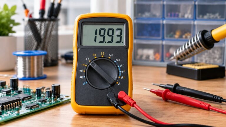
Set the meter to DC volts for any test with the car powered. Set it to resistance or continuity only for tests with the power off. Fluke describes a continuity beep as typically meaning resistance below about 25 to 50 ohms. Check your meter’s manual for its own beep threshold.
Step 1: check the headlight fuse
Find the headlight fuse in the owner’s manual or the fuse box diagram. The carsymp fuse and relay checklist describes the fuse test as confirming power on both sides of the fuse while the headlight circuit is commanded on. Turn the lights on and measure DC voltage on each side of the fuse. Power on both sides means the fuse is passing current. Power on the supply side but not the load side points to the fuse or its terminals.
The same checklist warns that a fuse can look intact and still fail to conduct because of poor terminal contact, so a visual check is not enough.
Step 2: check voltage at the headlight connector
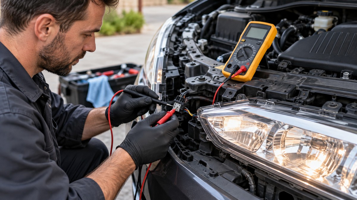
Next, check whether the headlight feed reaches the connector while the lights are on. Undergroundlighting describes this test with the bulb removed from the socket. Set the meter to DC volts, using the 20 V range if the meter does not auto-range. Turn the headlights on. Touch the red probe to the power terminal inside the connector and the black probe to a clean metal ground on the vehicle.
Undergroundlighting reads about 12 to 14 V as power reaching the bulb. A reading below about 12 V points to a weak ground, damaged wiring, corrosion or a loose connection that causes a voltage drop. A reading of 0 V means checking the fuse, relay, headlight switch, wiring or control module, depending on the vehicle. A 2010 forum reply on Car Talk uses the same method with the black lead on the frame or the negative battery terminal, and it expects around 12.4 volts on low beam. That figure comes from one forum reply, not from a manufacturer, so treat it as a rough check.
The sources do not give a cut-off that fits every car, so compare the reading with the other headlight on the same vehicle where you can.
Step 3: check the relay
Many headlight circuits switch the lamp through a relay, so a relay fault can look like a switch fault from the dashboard. The Drive relay article gives the DIN 72552 pin roles that many automotive relays follow. Pin 30 is the battery positive feed. Pins 85 and 86 are the coil, with 85 as coil negative and 86 as coil positive. Pin 87 is the common contact that connects to pin 30 when the relay energizes. Not every relay follows this layout, so check the wiring diagram.
For the coil test, remove the relay, set the meter to ohms, and measure between pins 85 and 86. The Drive article says a reading between 50 and 120 ohms means the coil is likely good, and a reading outside that range means the relay needs replacing. With the coil not energized, pins 87 and 30 should show no resistance between them. Those two checks separate the coil side from the contact side of the relay.
The carsymp checklist lists intermittent headlights, clicking with no output, or no click at all as relay failure symptoms. It also says a relay can click and still fail under load, so a click alone does not prove the relay is working.
Step 4: check the bulb off the car
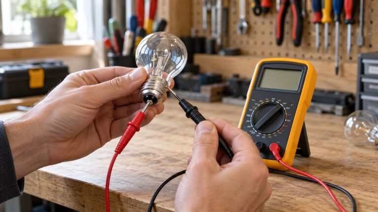
If the connector shows power and the relay checks out, test the bulb. Disconnect the battery negative terminal first, as the Fluke continuity guide advises. Unplug the headlight connector, remove the bulb, and touch the two meter probes together to confirm the meter beeps. Then touch one probe to each bulb contact. Undergroundlighting says a beep or a low-ohm reading means the filament is intact, and an OL or infinite reading means the filament is open and the bulb has failed.
Dual-filament bulbs need a separate check. Undergroundlighting describes a common ground terminal with separate low-beam and high-beam terminals, and says each filament should be tested on its own. If one filament reads well and the other shows OL, replace the bulb even though one side still lights.
Step 5: measure voltage drop with the lights on
The carsymp checklist describes voltage drop testing as measuring how much voltage is lost across a fuse, relay or connection while the headlights draw current.
The Fluke starter circuit article describes the method. Set the meter to DC volts, using a millivolt range if you expect drops under 1 V. Put the red probe on the supply side of the connection and the black probe on the load side, load the circuit, and read the drop. Fluke applies the same method to the positive and ground sides, one side at a time. For a headlight, the supply side is the feed through the fuse and relay, and the load side is the connector pin for the bulb.
The Fluke threshold for the starter circuit is 0.2 to 0.5 V total drop, about 0.3 V on the positive side and 0.2 V or less on the ground side, and Fluke says anything higher suggests corrosion, loose terminals or damaged cables. These figures are for the starter circuit only. The sources we opened do not give a voltage drop limit for headlight circuits, so do not apply the starter numbers to headlights. Compare the two sides of the same connection instead: the side with the bigger drop is the one to inspect first.
Step 6: check the ground path
The ground side is the return path to the battery negative. The carsymp checklist puts ground last in its order: power in, fuse, relay, power out, ground. The Car Talk reply connects the black lead to a good ground on the frame or the negative battery terminal during its voltage check. A poor ground shows up as a lower voltage at the connector, as step 2 describes.
Measure the ground side drop with the lights on, and compare it with the positive side. The Fluke starter guide gives 0.2 V or less as its ground side guideline. As in step 5, that figure is for the starter circuit and is not a headlight limit. A ground connection that drops much more than its partner side is the likely weak point.
Reading the results
| What you measure or see | What the sources say it points to |
|---|---|
| Fuse with power on both sides, lights on | The fuse is passing current; move to the connector |
| 0 V at the connector with lights on | Break upstream: check the fuse, relay, headlight switch, wiring or control module |
| Below about 12 V at the connector | Weak ground, damaged wiring, corrosion or a loose connection causing a voltage drop |
| Relay clicks but the light stays off | The relay may be failing under load; check the coil and contacts |
| Coil between pins 85 and 86 outside 50 to 120 ohms | The coil is likely bad and the relay needs replacing |
| Bulb filament reads OL | The filament is open and the bulb has failed |
| Bulb good, connector voltage good, lights still dark | Check the socket contact, the connector and the ground path |
The sources do not give one voltage that every headlight must read.
Common mistakes
- Testing a powered circuit in resistance or continuity mode. Fluke warns that this can damage the meter.
- Treating a good bulb as the end of the diagnosis. Undergroundlighting says a good bulb points back to the feed circuit.
- Applying the Fluke starter circuit numbers to headlights.
- Replacing a relay because it clicks. The carsymp checklist says a relay can click and still fail under load.
- Guessing pin numbers. The Drive article gives the DIN 72552 definitions as a standard, so check the diagram for your car.
Frequently asked questions
Do I have to remove the bulb to test the circuit?
For the connector voltage test, Undergroundlighting describes removing the bulb from the socket and turning the lights on. The filament check also needs the bulb out.
Why do I read 12 V at the connector but the headlight stays dark?
Undergroundlighting says the bulb may be bad under load, the socket contact may be loose, or the connector may be corroded. A correct voltage reading does not prove the socket, connector and ground path are all sound.
What does a relay click without a light mean?
The carsymp checklist lists clicking with no output as a relay failure symptom, and it says a relay can click and still fail under load. Test the coil and the contacts as described in step 3. The sources we opened do not say that a click alone proves the relay is good.
Do I need to disconnect the battery?
Disconnect the battery negative terminal, or make sure the circuit is not live, before any continuity or resistance test, as the Fluke continuity guide says. Voltage tests with the car powered do not need that.
Are LED headlights tested the same way?
Undergroundlighting notes that a 12 V LED headlight bulb usually has driver circuitry built into the bulb or attached to the wiring, so the bulb test in step 4 does not work the same way for LED bulbs. The sources we opened give no LED test steps. Check the manufacturer’s guidance before you test an LED bulb or module.
What we could not verify
The sources we opened do not say the following, and this guide does not claim them.
- A headlight-specific voltage drop limit from a manufacturer. The Fluke threshold is for a starter circuit.
- The pin layout for your car’s headlight relay and connector. The only layout cited is the general DIN 72552 relay standard.
- A CAT rating for any meter beyond the Klein MM400 and Fluke 15B and 17B manuals.
- How to tell a burnt relay contact from a weak coil with a multimeter alone.
- Test steps for LED headlights. One source says LED bulbs usually carry driver circuitry, but none of the sources opened gives a test procedure.
- A cut-off that separates a healthy connector from a weak ground on every car. The 12 to 14 V band comes from one retail blog, and the 12.4 V figure from one 2010 forum reply.
Related guides
For meter choice, see our roundup of multimeters for beginners. For fuse and wiring checks, see our guide to using a continuity tester. For a quick check of which wires carry voltage, see using a non-contact voltage detector.
Sources
- Klein Tools MM400 user manual: https://www.eoas.ubc.ca/courses/atsc303/Instruments/manuals/0_Klein-Tools-MultiMeter-MM400-UsersManual.pdf
- Fluke 15B and 17B user manual: https://assets.fluke.com/manuals/15b17b__umeng0400.pdf
- Fluke, automotive continuity checks: https://www.fluke.com/en-us/learn/blog/digital-multimeters/how-to-perform-automotive-continuity-checks-with-a-multimeter
- Fluke, starter circuit voltage drop: https://www.fluke.com/en-us/learn/blog/digital-multimeters/how-to-check-starter-circuit-voltage-drop-with-a-multimeter
- Undergroundlighting, how to test a headlight bulb with a multimeter: https://undergroundlighting.com/blogs/headlight/how-to-test-a-headlight-bulb-with-a-multimeter
- Carsymp, headlight fuse and relay troubleshooting: https://carsymp.com/auto-electrical-repair/headlight-repair/headlight-fuse-and-relay-troubleshooting/
- The Drive, how to test a relay: https://www.thedrive.com/maintenance-repair/36048/how-to-test-a-relay.md
- Car Talk community, how to test a car’s headlight connector (2010 forum replies): https://community.cartalk.com/t/how-to-test-a-cars-headlight-connector/53657