How to Test a Light Bulb With a Multimeter
As an Amazon Associate we earn from qualifying purchases.
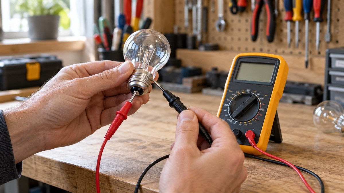
How to test a light bulb with a multimeter comes down to four moves: take the bulb out of its socket, switch the power off, set the meter to continuity or ohms, and touch the two probes to the two electrical contacts on the bulb base. A beep or a low reading means the meter found a complete path through the bulb. An OL reading means the meter sees an open circuit. This guide covers low-voltage bulbs only, such as bench bulbs and automotive bulbs with a stated low voltage.
Electrical safety comes first
Work on mains circuits can kill. OSHA says its electrical standards are designed to protect employees from dangers such as electric shock, electrocution, fires, and explosions. The Klein MM400 manual warns that failure to observe its warnings “can result in severe injury or death.” OSHA’s electrical hazards eTool for poultry plants explains that electric shock occurs when the body becomes part of an electric circuit. The Klein manual also warns that voltages above 25 V AC RMS or 60 V DC pose a shock hazard.
Before you measure anything, check that the meter’s CAT rating suits the circuit you are testing, and read the rating from the listing or the manufacturer’s manual. Fluke advises choosing a test tool rated to the highest category and voltage it could possibly face. Fluke’s ENEN safety guide describes CAT IV as the origin of an installation, where the connection is made to utility power, and its safety guide lists single-phase receptacle connected loads under CAT II. The GAMBICA overvoltage guide likewise places socket outlets in measurement category II. This guide names no meter, so it states no CAT rating for any model.
Panel and service work belongs to a licensed electrician. OSHA’s poultry eTool says that maintenance employees who perform electrical repairs should be qualified electricians, and it says equipment should be de-energized before inspection or repair. Household mains bulbs in a socket are out of scope, so this guide gives no steps for them.
Quick answer
- Test the bulb out of its socket, with the power off.
- Set the meter to continuity or ohms, and confirm the leads read near 0 Ω when touched together.
- Treat a beep or a low reading as a complete path, and an OL reading as an open circuit.
Preparation
You need a multimeter with a continuity setting and an ohms setting, two test leads, and a bulb that is out of its socket. On many meters the two settings share one position on the dial. Fluke notes that continuity, capacitance and diode functions often sit on the same position as ohms, and some models need a button press before continuity mode is active. On the Klein MM400 manual copy, the meter starts in continuity mode, and one press of the SEL button switches it to resistance.
Connect the black lead to the COM jack and the red lead to the VΩ jack. Fluke’s continuity steps use that pairing. The Klein manual uses the same pairing, with red in the V jack and black in COM. Remove the leads in reverse order when you finish, red first and then black, as Fluke advises.
Check the leads before you read the bulb. Fluke says that when the leads touch, the display should show 0 Ω. For very low readings, its relative mode subtracts lead resistance, which Fluke puts at typically 0.2 Ω to 0.5 Ω. The Klein manual asks you to verify meter operation before each use by measuring a known voltage or current, which is a voltage and current check rather than a resistance check, so the lead check above is the one that applies here.
Replace the batteries when a low battery indicator appears. The Klein manual says this avoids false readings that can lead to electrical shock, and it advises against opening the meter to change batteries while the probes are connected.
Steps to test the bulb
-
Switch the power off and remove the bulb from its socket. Fluke’s resistance guide begins with “Turn Off Power to Circuit,” and it says the best results come when the component is removed from the circuit. The Klein manual gives the same rule as “Remove power from circuit.” The GSU lab handout also disconnects the leads from the bulb before it reads the filament.
-
Set the meter to continuity or to ohms. Fluke’s continuity guide says the meter emits a beep when it detects a complete path. Resistance mode gives a number instead. In resistance mode, the Klein manual says that open test leads show O.L. and that this is normal.
-
Touch the two metal tips to the two electrical contacts of the bulb base. Fluke’s instruction is to connect the test leads across the component being tested and to make sure the contact is good. For a screw-base bulb, those contacts are the base tip and the threaded shell. The sources do not describe a contact layout for any bulb, so that placement is our own assumption.
-
Keep your fingers off the metal probe contacts while you read. The Klein manual tells the user to keep fingers away from them when making measurements, and Fluke says the human body becomes a parallel resistance path, lowering total circuit resistance.
-
Read the display or listen for the beep. Fluke’s continuity guide says the DMM will not beep if the circuit is open. The Klein manual says an open circuit shows OL in continuity mode. Write down the reading before you move the probes.
-
Record the room temperature with the reading. The GSU handout notes the current room temperature when it records the cold filament resistance. Compare the result with a known good bulb of the same type, which is our own assumption, because the sources do not give a reference value for any bulb.
-
Switch the meter off when you finish. Fluke gives this step as “Turn Multimeter OFF to Prevent Battery Drain.”
For the general continuity method, see our guide to how to use a continuity tester. For continuity testers in general, see our continuity tester roundup.
Reading the results
An OL reading means the meter sees an open path. The Klein manual says that an open circuit shows “OL,” and Fluke says that with the probes separated the display may show OL and Ω. For a bulb, an OL reading points to a broken filament path. That last link is our own inference, because none of the sources we opened says so for a bulb in those words. Confirm that the leads make contact before you accept an OL reading.
A beep or a low reading means the meter found a complete path. The Klein manual sets its audible signal at a resistance below 50 for that model, which makes the threshold a property of that meter and not a general rule. Fluke’s resistance guide adds that the display can show a value that reflects every path between the probe tips, so a low reading is not proof of a good filament on its own.
A resistance reading taken with the bulb cold is not the value the bulb has when it glows. The CSULB physics lab says that in metals the resistance increases with temperature, and the GSU handout says that as the filament of an incandescent bulb heats up and cools down, its resistance changes significantly. The DePaul handout gives the nominal operating temperature of an incandescent filament as 2575 K, which it describes as over eight times room temperature (293 K). It also asks students to calculate the resistance when the filament is hot and glowing and when it is cold and dark.
The NIST report SP 260-90 gives recommended electrical resistivity values for tungsten from 2 K to 3000 K. The sources we opened do not convert that table into a bulb reading, so this guide quotes no number from it. Because the sources give no resistance value for any particular bulb, this guide gives no expected ohm figure. Judge a reading against a known good bulb of the same type, which is our own assumption.
Common mistakes
-
Testing with the power on. The Klein manual says “DO NOT attempt to measure resistance on a live circuit.” Fluke’s continuity steps also say to test with the circuit de-energized.
-
Leaving the bulb wired into a circuit. Fluke says the resistance of all components connected in parallel with the part under test affects the reading, usually lowering it. Remove the bulb so that no parallel path is left.
-
Holding the probe tips. Fluke explains that the human body becomes a parallel resistance path, so a finger on a metal tip can pull the reading down.
-
Ignoring dirty contacts. Fluke lists foreign substances such as dirt, solder flux and oil as a cause of wrong resistance readings. Clean the bulb base contacts before you conclude that the bulb has failed. This is a general point from Fluke and not a bulb-specific test.
-
Skipping the lead check. If the leads themselves read a few tenths of an ohm, that offset belongs to the leads. Use relative mode for very low readings, as Fluke describes.
-
Treating OL as proof without checking contact. Fluke’s resistance guide says the display should show OL before the leads connect to anything, so an OL reading alone does not show where the fault is.
How we chose
We chose sources that answer one of three questions: how a meter is set and read for resistance or continuity, what the electrical safety limits are, and how a bulb filament behaves electrically. We kept manufacturer pages and manuals from Fluke and Klein, university lab pages and handouts from Georgia Perimeter College, DePaul University and California State University Long Beach, and government pages from OSHA and NIST. We added one UK trade association guide for the CAT wording. Each source is one we opened and read on 2026-10-21. The Fluke, Klein and university handouts all describe measuring a part with the power off and the part out of its circuit, so this guide uses that method. We left out retailer listings and blog posts for any procedure or safety claim. We dropped pages that returned 403 or did not load, and we did not rank or recommend any meter.
What we could not verify
The sources we opened do not give a resistance value for any bulb model, so this guide states no expected reading. They do not cover LED or CFL bulbs, so this guide does not cover them. They do not describe how to confirm a bulb’s stated voltage before a test, and they do not give automotive bulb ratings. The audible threshold of less than 50 belongs to one manual copy, and the sources do not say whether other meters use the same value. The NIST report gives tungsten resistivity values, but the sources we opened do not link those values to a bulb reading. The sources also do not give the size of the hot-to-cold change for any bulb.
Frequently asked questions
Can I test a bulb while it is still in the lamp?
No. Fluke and Klein both tell the user to cut power and take the part out of the circuit before a resistance reading. Fluke adds that parallel parts change the answer, so a bulb left in a lamp can read wrong even with the power off.
What does OL mean on the display?
On the Klein MM400 manual copy, OL means the circuit is open in continuity mode. Fluke uses the same symbol when the probes are separated, so an OL reading alone does not show that a bulb has failed.
Does a beep prove the filament is good?
No source we opened says so. A beep shows only that the meter found a path, and the threshold that triggers it is set by the meter itself. The Klein manual gives its figure for one model.
Why does a hot bulb read differently from a cold one?
The CSULB physics lab states that in metals the resistance increases with temperature, and the GSU handout says a conductor’s resistance depends on its temperature. A cold ohmmeter reading therefore describes the filament at room temperature. The sources do not give the size of the change for any particular bulb.
Can I use this method on LED bulbs?
This guide does not cover LED or CFL bulbs, and the sources we opened do not describe a test for them. Check the bulb maker’s instructions for those types before you probe the base.
Can I test a bulb in a mains lamp this way?
No. A lamp plugged into a wall outlet falls outside this guide, and the safety section above applies. If the lamp’s wiring or socket needs work, a qualified electrician should handle it.
Sources
- https://www.fluke.com/en-us/learn/blog/digital-multimeters/how-to-measure-resistance (opened 2026-10-21)
- https://www.fluke.com/en-us/learn/blog/digital-multimeters/how-to-test-for-continuity (opened 2026-10-21)
- https://www.fluke.com/en-us/learn/blog/safety/multimeter-guide (opened 2026-10-21)
- https://images.a.fluke.com/Web/FlukeCorporation/%7Bc9b14f7e-6772-4153-9825-e5459efe2f56%7D_ENEN-safety_pages.pdf (opened 2026-10-21)
- https://images.toolsid.com/install-bay/items/pdf/mm400-manual.pdf (opened 2026-10-21)
- https://sites.gsu.edu/claphast/files/2017/08/OhmsLaw-2d6ma2c.pdf (opened 2026-10-21)
- https://condor.depaul.edu/rmorriso/labs/lab1.pdf (opened 2026-10-21)
- https://home.csulb.edu/~tgredig/phys152lab/electric-circuit-with-light-bulb.html (opened 2026-10-21)
- https://www.osha.gov/electrical (opened 2026-10-21)
- https://osha.gov/etools/poultry-processing/plant-wide-hazards/electrical-hazards (opened 2026-10-21)
- https://www.nist.gov/system/files/documents/2016/10/06/SP260-90.PDF (opened 2026-10-21)
- https://www.gambica.org.uk/static/d96bb734-348d-478e-b0cba3b50fc35940/Guide-to-Overvoltage-Categories-and-Measurement-Categories.pdf (opened 2026-10-21)