How to Check an NPN Transistor With a Multimeter
As an Amazon Associate we earn from qualifying purchases. Details
Updated 19 October 2026
Author: Editorial team, bestmultimeter2020.com
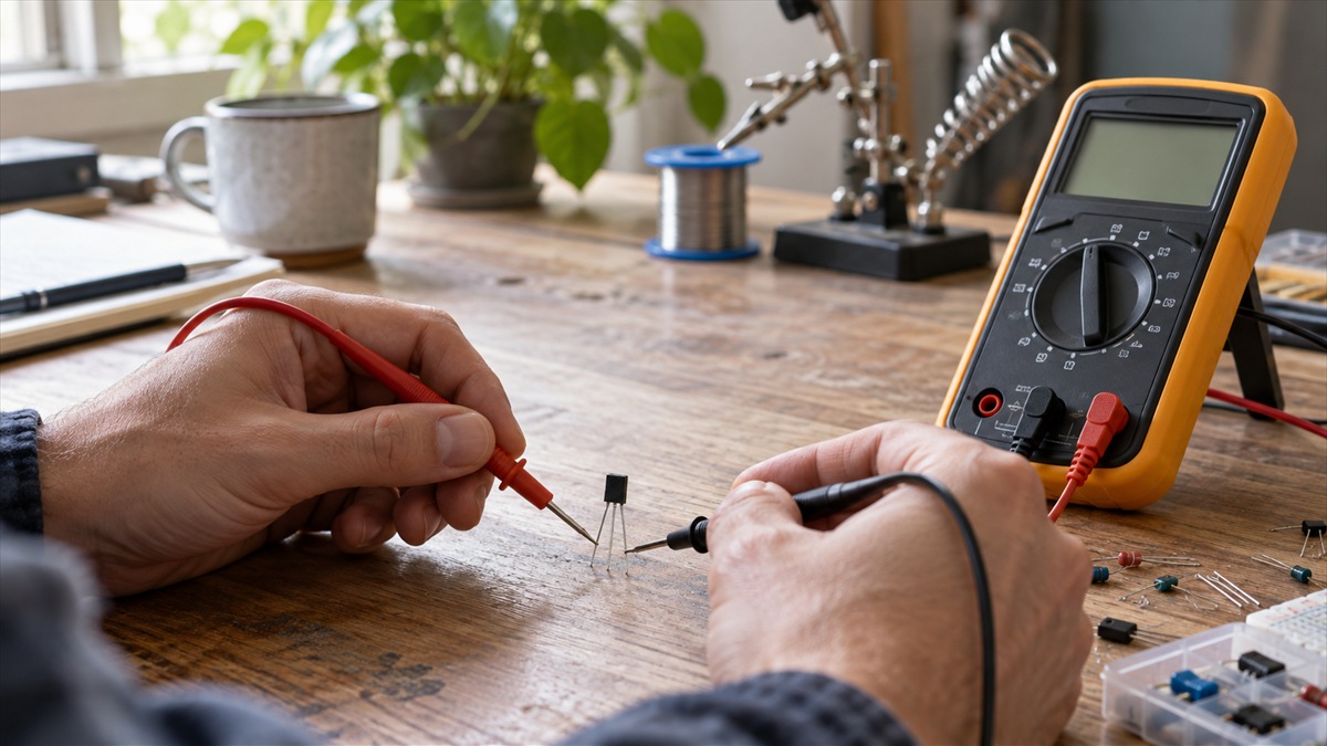
An npn transistor check with a multimeter is a junction check. An NPN transistor has two PN junctions, one between the base and the emitter and one between the base and the collector. Each junction behaves like a diode, so a multimeter in diode mode can show whether each one conducts in the forward direction and blocks in reverse. The check tells you whether the junctions look normal. It does not tell you the transistor’s gain, and a normal result does not prove the device works in a circuit.
Quick answer
- Power off the circuit, discharge any capacitors, and take the transistor out of the circuit before the check.
- Use diode mode. With the red lead on the base, a good NPN shows a forward drop on the base-emitter and base-collector junctions. With the leads reversed, a good junction reads OL.
- The diode check does not measure current gain (hFE). Read the results as a junction check only, and compare with a known good part of the same type where you can.
What you are checking
The Kuphaldt text on transistor meter checks describes the transistor as two diodes connected back to back when it is checked with a multimeter’s resistance or diode check function. For an NPN, the base is the P-type material between two N-type regions. That is the reverse of the PNP, so the forward and reverse directions swap when you move from a PNP to an NPN.
The practical result is simple. On an NPN, the base-emitter and base-collector junctions conduct when the base is positive relative to the emitter or collector. A multimeter’s red lead is positive in resistance and diode mode on most meters, which is why the red lead goes on the base for the forward check. The Fluke learn article on diodes explains that the diode test applies a small voltage between the leads, enough to forward-bias a junction, and that is the same principle at each junction here.
The Kuphaldt text also notes that some multimeters have two continuity functions, resistance and diode check, “each with its own purpose.” For transistor junctions, use the diode check. The resistance function is less reliable for a junction check, as the next section explains.
Before you start: power, capacitors and removal
Switch the circuit off and confirm it is de-energized before you touch the transistor. The Fluke resistance guide advises discharging any capacitor in the circuit before a resistance reading, and the same care applies to a diode check on a board with capacitors. A charged capacitor can give a misleading reading and can be a hazard in its own right.
Take the transistor out of the circuit if you can. The Fluke resistance guide says the best results come when the component is removed from the circuit, because other paths in the circuit lower the reading. A transistor in a board is connected to resistors, capacitors and other semiconductors, and each one can change what the meter shows. If you cannot remove the part, read the results as a rough screen only.
Identify the pins before you start. The sources we opened do not give pin layouts for common transistor packages, so the datasheet for your exact part is the only reliable source for which lead is the base, the emitter and the collector. Mark the pins on paper before you connect the leads, because a wrong pinout gives results that look like faults.
Step by step in diode mode
Set the meter to the diode test symbol. The Fluke diode guide calls diode test mode the more effective method for a diode, and it says resistance mode is less reliable and should only be used if the meter has no diode mode. Then make these five checks, in order.
- Forward base-emitter: red lead on the base, black lead on the emitter. A good silicon junction shows a forward drop in the range the Fluke guide gives.
- Forward base-collector: red lead on the base, black lead on the collector. Expect a similar drop.
- Reverse base-emitter: black lead on the base, red lead on the emitter. A good junction reads OL.
- Reverse base-collector: black lead on the base, red lead on the collector. A good junction reads OL.
- Collector-emitter in both directions: the sources we opened do not give an expected value for this pair, so record the readings and do not judge the part on them alone.
The table below sets out the expected results and the common fault patterns. The forward range comes from the Fluke diode guide, and the typical silicon value comes from the Fluke 87 manual.
| Check | Red lead | Black lead | Expected on a good NPN | Common fault pattern |
|---|---|---|---|---|
| Forward B-E | Base | Emitter | Forward drop, about 0.5 to 0.8 V | OL in both directions suggests an open junction |
| Forward B-C | Base | Collector | Forward drop, about 0.5 to 0.8 V | Near-zero reading in both directions suggests a short |
| Reverse B-E | Emitter | Base | OL | A forward drop here suggests the junction conducts both ways |
| Reverse B-C | Collector | Base | OL | A forward drop here suggests the junction conducts both ways |
The Fluke diode guide gives the range this way: “A good forward-bias diode displays a voltage drop from 0.5 to 0.8 volts (for most silicon diodes).” It adds that “The meter will display ‘OL’ when a good diode is reverse-biased.” The Fluke 87 manual says that for a silicon diode the typical forward voltage should be about 0.6V. That manual also describes the diode test as a single 0 to +3.000V range, so the meter’s diode test does not read beyond about 3 V.
Reading the results
A good junction shows a forward drop and OL in reverse. If both directions show the same reading, the Fluke diode guide treats the junction as bad, and the same logic applies to each base junction on the transistor.
Compare the two forward drops with each other. A simple difference shows whether the two junctions match.
Difference = larger forward drop minus smaller forward drop.
For example, suppose the base-emitter reading is 0.62 V and the base-collector reading is 0.58 V. Then the difference is 0.62 minus 0.58 = 0.04 V. Both values sit inside the 0.5 to 0.8 V range, and both are close to the 0.6 V typical figure. This example is illustrative arithmetic. The numbers are not readings from any part, and the sources do not say how big a difference is acceptable on any particular transistor.
If one junction is outside the range and the other is inside it, treat the part as suspect and compare with a known good part of the same type. The sources do not say what difference counts as a fault, so do not set a limit from this guide alone.
What the diode check cannot tell you
The diode check tests the two junctions. It does not measure current gain, which is the ratio of collector current to base current. The sources we opened do not describe a gain measurement with a standard multimeter, so this post does not claim one. Use the hFE function on a meter that has one, or a transistor tester designed for gain, and read the manual for the method.
The 3 V limit on the diode range also matters for some transistors. The Fluke 87 manual lists a single 0 to +3.000 V range for the junction test, so a junction that needs a higher test voltage will not read in the same way. The sources we opened do not say how this limit affects every transistor type, so check the datasheet for any voltage the device is rated for.
Results taken in a circuit can mislead. The Fluke resistance guide says that the resistance of components in parallel with the part being checked affects the reading and usually lowers it. The same logic applies to a diode check on a transistor that is still soldered in place, so a clean result in circuit is a weak result, while a fault in circuit is worth checking out of circuit.
Resistance mode is not the right tool for this check. The Fluke diode guide says resistance checks are less reliable and should only be used when the meter has no diode mode. Diode mode reports the forward voltage across the junction directly, which is the number this check needs.
A note on pinouts and packages
The base, the emitter and the collector are not always in the order you expect, and pin order differs between packages. The sources we opened do not show pin layouts, so do not rely on a picture of the package. Check the datasheet, mark the leads and recheck the layout if the first results look odd.
If the transistor is a surface-mount part, the leads may be hard to reach with the probes. The sources do not describe surface-mount checks, so this post does not give steps for those packages. Take care to avoid bridging two pins with the probe tips, because a bridge reads as a short and can be mistaken for a fault.
Safety
This is a low-voltage check on a semiconductor, but it still starts with the circuit switched off and de-energized. Discharge capacitors before you connect the leads. The Fluke resistance guide advises the same step for resistance readings, and it is a good habit for any junction check.
Check the meter’s CAT rating and fuse before use, and replace damaged leads. The Fluke safety guide says a damaged meter or damaged test probes should never be used. A transistor check is not a mains task, and this guide does not cover mains circuits. Any work on a circuit connected to mains, a panel or a power supply that is still energized belongs to a licensed electrician.
How we chose
We chose the Kuphaldt LibreTexts meter-check pages for the junction logic and the NPN and PNP relationship, because they explain the junction behavior in detail. We used the Fluke diode guide and the Fluke 87 manual for the forward range, the OL reading and the diode test range, since both describe a meter’s diode function directly. The Fluke resistance guide supplies the removal and discharge advice. We did not use Wikipedia, retailer pages or blogs for any procedure or safety statement. The guide lists no products and gives no prices.
What we could not verify
- The sources we opened do not give the expected collector-emitter reading for an NPN with a diode check, so this post does not state one.
- The sources do not measure or describe current gain with a standard multimeter.
- The sources do not give pin layouts for common transistor packages, so the pinout must come from the datasheet.
- The sources do not state how much difference between two forward drops counts as a fault.
FAQ
What does an NPN transistor check with a multimeter show?
It shows whether the two base junctions conduct in the forward direction and block in reverse. A good junction gives a forward drop in the range the Fluke diode guide gives, and OL in reverse. It is a junction check, not a gain check.
Why use diode mode instead of resistance mode?
The Fluke diode guide says diode mode is by far the more effective method, and resistance checks are less reliable. Diode mode applies a small voltage that forward-biases the junction, which gives a direct reading. Use resistance mode only if the meter has no diode mode.
Can a multimeter measure the gain of a transistor?
The sources we opened do not describe a gain measurement with a standard multimeter. Some meters have an hFE function. If yours does, follow the manual. If it does not, use a transistor tester designed for gain.
What does OL mean on a transistor junction?
OL means the meter sees no conduction, which is the reading you want for a reverse-biased junction. On a forward check, OL in both directions can mean an open junction, as the table above shows.
Can I check a transistor while it is still in the circuit?
You can take a rough reading, but the results can be misleading. The Fluke resistance guide says other paths in the circuit affect the reading. For a clear result, remove the transistor, check it with power off and discharged capacitors, and compare with a known good part.
Bottom line
For an NPN, check the base-emitter and base-collector junctions in diode mode with power off and the part out of circuit. A forward drop with the red lead on the base and OL with the leads reversed is the normal pattern. A diode check does not measure gain, so confirm the part with a gain test or a known good comparison before you decide it is good.
For the continuity side of the same meter, see diode continuity test. For a general continuity check, see how do I use a continuity tester.
Sources
- LibreTexts: Meter Check of a Transistor (BJT), Kuphaldt: the two-junction model, the PNP check that reverses for an NPN, and the two continuity functions
- LibreTexts: Meter Check of a Diode, Kuphaldt: the qualitative nature of an ohmmeter diode check and the reverse reading
- Fluke learn: What is a diode?: the diode test mode, the 0.5 to 0.8 V forward drop, the OL reverse reading and the bad-diode rule
- Fluke 87 true RMS multimeter users manual (PDF): the 0.6 V typical silicon forward voltage and the 0 to 3 V diode range
- Fluke learn: How to measure resistance with a digital multimeter: removing the component from the circuit, discharging capacitors and parallel paths