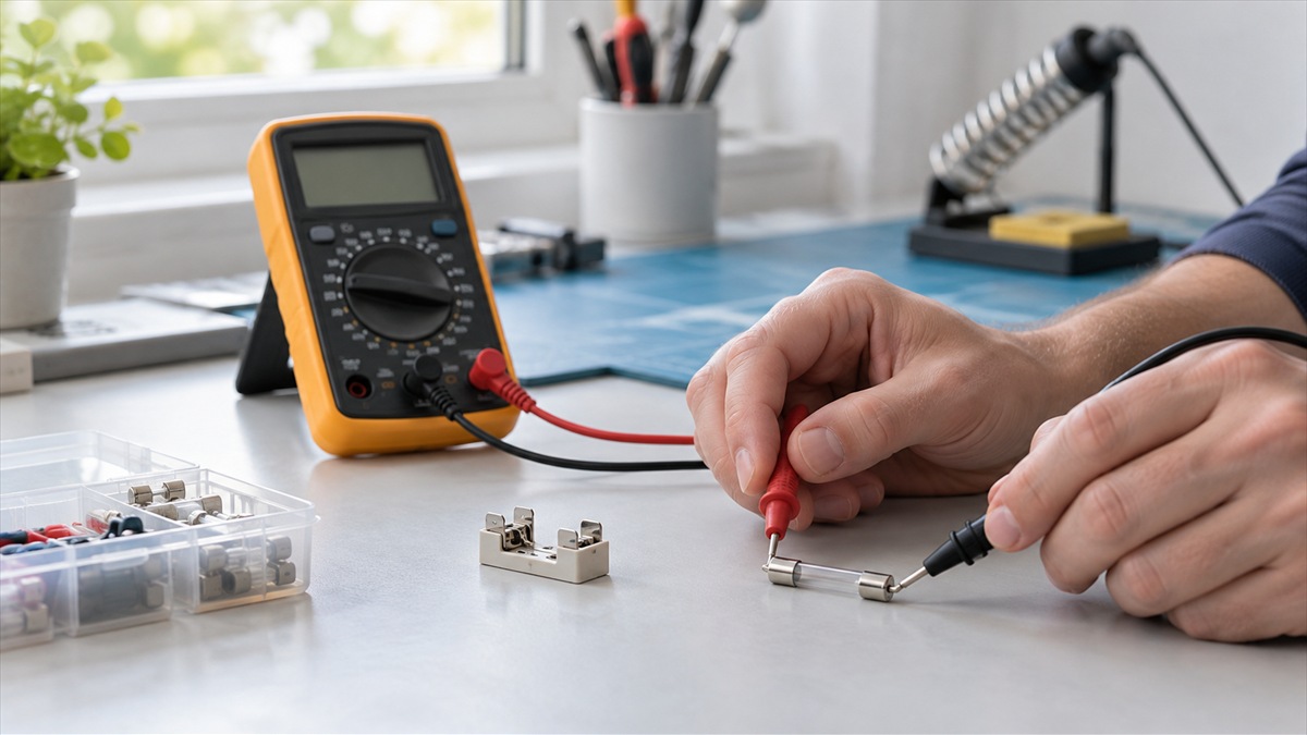
How to Check a Fuse With a Multimeter
As an Amazon Associate we earn from qualifying purchases. Details
Updated 19 October 2026
Author: Editorial team, bestmultimeter2020.com
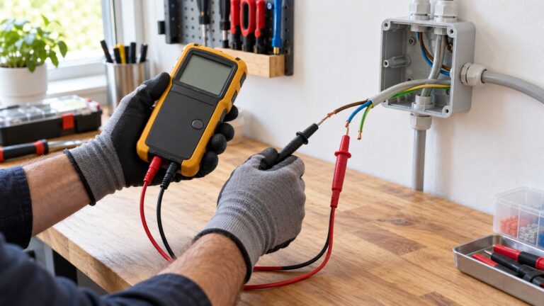
This guide explains how to check a fuse with a multimeter. Switch the power off, confirm the circuit is de-energized, remove the fuse, and set the meter to continuity or ohms. A beep, or a reading close to 0 ohms, means the fuse is intact. No beep, or an OL reading, means it is blown. The sources we opened give no separate test steps for glass tube, ceramic, blade or plug-in fuses, so the safety steps and the lead-resistance arithmetic matter most.
Quick answer
- Confirm the circuit is dead first. Switching it off is not enough. Test with a voltage tester before the probes touch anything.
- Use continuity mode when you can. Fluke prefers it for fuse checks because it gives an audible signal.
- Read the display. A beep or a low reading (usually 0 ohms or close to it) means intact. No beep, or OL, means blown. Then do the visual check.
- Replace it with the same type and rating. Match the fast-acting or time-delay type, the amp rating, and the voltage rating.
Before you start: safety and setup
The Fluke guide opens its safety advice with a clear rule: “Before starting any electrical testing, ensure the circuit you’re working on is powered off and disconnected from any power source to avoid electrical shock or further damage to the circuit.” It adds: “Also wear appropriate personal protective equipment (PPE), such as insulated gloves and safety glasses.”
Verify the circuit is de-energized
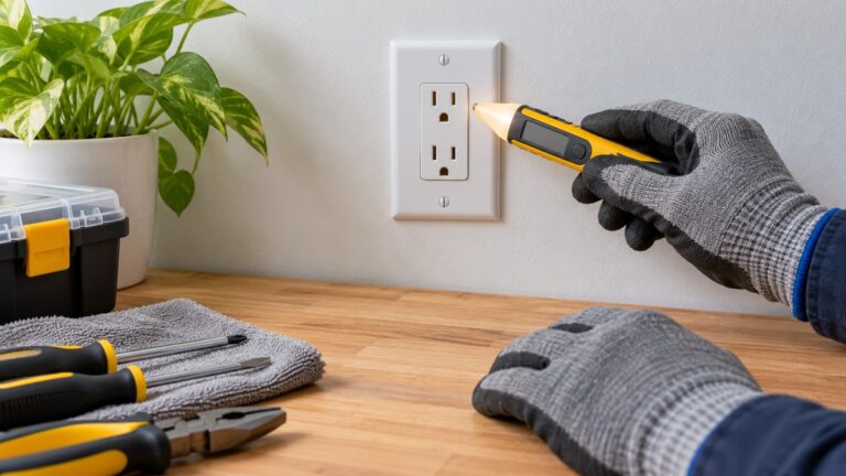
Power off is not proof. Fluke’s absence-of-voltage guide says: “Even when equipment appears to be shut down, voltage can still be present.” Its advice is direct: “You must use a voltage tester to confirm it’s actually dead.” Fluke also notes that “Safety standards like NFPA 70E require use of the Live-Dead-Live test”, which checks the tester on a known live source before and after the measurement.
The OSHA rule for workplace equipment works the same way. Under 29 CFR 1910.333(b)(2)(iv)(B), a qualified person must verify that parts are de-energized: “shall verify that the circuit elements and equipment parts are deenergized.” Those sources are written for workplaces. The sources we opened do not say how to apply this test to a household appliance or a car, so if you cannot confirm that the circuit is dead, stop.
Check a fuse only when its circuit is de-energized and disconnected from the power source. This guide does not cover checking a fuse while the circuit is still energized. If the fuse sits in a breaker panel, a service disconnect, or equipment you cannot fully de-energize, stop and call a licensed electrician.
Check the meter before you rely on it
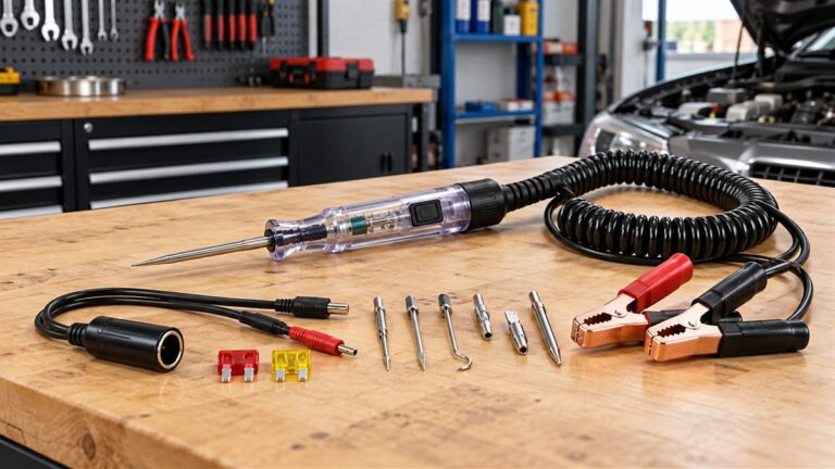
Fluke’s multimeter safety guide says: “You should never use a damaged meter or damaged test probes.” Before you read any fuse, touch the two probes together in continuity mode, as Method 1 explains. If you want a dedicated tool for quick checks, our fuse tester pen guide covers that category.
Fuse types
The sources we opened describe four styles. The method below works for any fuse you can remove from its holder.
- Glass tube. “Used in older-model cars, glass tube fuses today are found primarily in automotive accessory applications.” The Bussmann catalog lists fast-acting and time-delay glass tube fuses.
- Ceramic tube. “Both glass and ceramic tube fuses vary by diameter and length.” The catalog lists time-delay ceramic tube fuses and notes that “Generally, two sizes of user-replaceable fuses are found: the 1/4″ x 1-1/4″ and 5×20 mm.”
- Blade. The catalog’s specification table lists blade families, including a “Mini fuse” (ATL) and the ATC, ATM, ATR and MAX codes. The sources we opened give no contact points or test steps for this type.
- Plug-in (Edison base). “Edison base threads into non-rejection fuse receptacles.” The Edison catalog lists Type T dual-element, time-delay plug fuses rated 125 Vac or less, from 3/10 to 30 A. Rejection-base types are covered in the FAQ.
Method 1: check the fuse in continuity mode
Continuity mode is the easiest method for most fuses. Fluke says: “Continuity mode is generally preferred for fuse testing as it provides a clear, audible signal if the fuse is intact.”
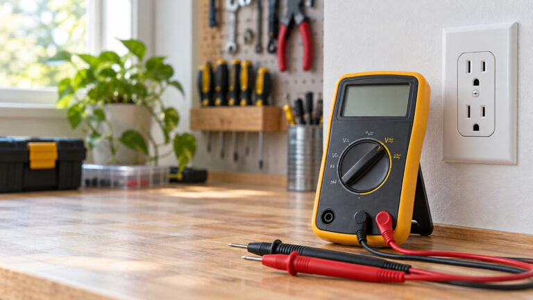
- Set the dial. Turn the dial to the continuity symbol. If your meter combines continuity with another mode on the same dial position, use the continuity setting.
- Check the meter. Touch the two probes together. The fuse guide says the meter “should emit a beep, indicating it’s working correctly.”
- Place the probes. “Position the multimeter probes on each end of the fuse.”
- Read the result. A beep means a complete path through the fuse, so the fuse is good. No beep means it is blown.
Two details decide whether the beep is trustworthy. First, “Loose or poor contact can lead to inaccurate readings.” Second, the fuse must be out of its holder. The fuse guide says: “Remove the fuse from its holder.” If your meter has no continuity mode, read how to use a continuity tester first, then use the ohms method below.
Method 2: check the fuse in resistance (ohms) mode
Use ohms mode when continuity is not available. The fuse guide says: “In resistance mode, you should see a low resistance reading (typically 0 or close to it).” The resistance guide notes that the display “should show OLΩ” before any connection, so OL on its own does not mean the fuse is blown.
Set the dial to ohms and touch the leads together. “Ideally, if test leads touch (are shorted together), the display should show 0 Ω.” If the display does not go close to zero, fix the leads or the meter before you read the fuse. Then place one probe on each end of the fuse and read the display.
What the readings mean
| What the meter shows | What the Fluke fuse guide says it means | What to do next |
|---|---|---|
| Beep in continuity mode | The fuse is good, with a complete path | Do the visual check |
| No beep in continuity mode | The fuse is blown | Replace it after the visual check |
| Low reading, usually 0 ohms or close to it | The fuse is intact | Do the visual check |
| OL, or infinite resistance (often shown as 1) | The fuse is blown | Replace it |
Read OL only after the probes are on both ends of the fuse and making good contact. OL also appears before the probes touch anything.
Subtract the lead resistance
The resistance guide explains the relative mode: “It automatically subtracts test lead resistance—typically 0.2 Ω to 0.5 Ω.” If your meter has a REL (relative) mode, use it. If not, use this formula:
fuse resistance = displayed reading minus lead resistance
Because the lead resistance is 0.2 to 0.5 ohms, the fuse alone sits between the displayed reading minus 0.5 ohms and the displayed reading minus 0.2 ohms.
Worked example one: the display reads 0.5 ohms. The lower limit is 0.5 minus 0.5 equals 0.0 ohms. The upper limit is 0.5 minus 0.2 equals 0.3 ohms. So the fuse alone is between 0.0 and 0.3 ohms, a low value that points to an intact fuse.
Worked example two: the display reads 1.0 ohms. The lower limit is 1.0 minus 0.5 equals 0.5 ohms. The upper limit is 1.0 minus 0.2 equals 0.8 ohms. The sources we opened give no numeric cut-off between a low and a high reading, so use the beep and the visual check together with the number.
Visual check after the reading
The Fluke guide says: “Look for obvious signs of damage, such as a broken wire inside the fuse or a darkened, burnt appearance.” A fuse with a low reading but a broken wire or burn marks should be treated as blown. Do not put it back in the circuit.
Replacing a blown fuse
Replace the fuse with the same type and rating. The Eaton Bussmann catalog says: “Any replacement fuse must match the one it’s replacing.” In practice that means three matches:
- Characteristic. Fuses “must match required fuse characteristic – either fast-acting or time-delay.”
- Amp rating. “Amp rating must match that of the original fuse.”
- Voltage rating. It must match or exceed the rating of the fuse being replaced. The FAQ covers the one case where a higher voltage is allowed.
Checking the meter’s own internal fuse
Your meter has its own fuse, separate from the circuit fuse. A textbook on ammeters explains that “Ammeters are generally protected from excessive current by means of a small fuse located inside the meter housing.” It adds that you “may test the condition of a multimeter’s fuse by switching it to the resistance mode and measuring continuity through the test leads (and through the fuse).”
If an ammeter is connected by mistake across a voltage source, the surge in current “will “blow” the fuse and render the meter incapable of measuring current until the fuse is replaced.” If your current range suddenly stops reading, check the meter fuse before you blame the circuit. Where the current jacks differ from the voltage jacks, follow your meter manual for the probe positions.
Common mistakes
- Checking with power on. Fluke is blunt: “Always ensure the power is completely disconnected before testing a fuse.”
- Skipping the probe check. A flat battery or a broken lead can give a misleading reading.
- Reading OL too early. Read OL only with the probes on the fuse ends.
- Ignoring parallel paths. “The resistance of all components connected in parallel with a component being tested affects the resistance reading, usually lowering it.” Check the schematic first.
- Dirty or loose contact. Keep fingers off the metal tips, and clean the fuse ends if they look dirty.
Choosing a meter for fuse work
The Fluke safety guide says to “always choose a tool rated for the highest category you could potentially use it in”. CAT-rated meters are designed “to minimize or reduce the possibility of an arc flash occurring inside the meter.” The rating is “usually located near the input jacks.” This guide does not cover panel or service work, whatever the meter’s rating.
For current measurement rather than fuse checks, see our clamp meter guide.
How we chose
We picked sources that give step-by-step checks and say something specific about safety, fuse types or ratings. Fluke makes meters, so its pages are used for measurement steps, reading meaning and voltage-check guidance only. The Bussmann and Edison catalog copies supply fuse types and replacement matching; they are hosted by electrical distributors, and the text is the manufacturer’s. The OSHA rule is quoted from the Cornell Legal Information Institute copy, because osha.gov did not return text to our download. We did not use Wikipedia for any safety or procedure claim, and we did not use retailer or blog pages. The guide lists no products. We opened each source on 19 October 2026 and quote only sentences found in the saved text.
What we could not verify
- The sources we opened do not cover checking a fuse while the circuit is still energized.
- The sources we opened give no test steps or contact points for blade or plug-in fuses.
- The sources we opened do not cover a household appliance or a car. Follow the equipment manual for that step.
- The sources we opened give no numeric cut-off between a low and a high ohms reading.
- The sources we opened do not confirm that circuit-fuse reading thresholds apply to a meter’s internal fuse.
- The sources we opened do not cover breaker panels or service equipment.
FAQ
How can I tell a fast-acting fuse from a time-delay fuse?
The catalog says the type “can generally be visually identified.” Fast-acting fuses are “a single strand of wire or strip of metal”; time-delay fuses “usually have a coiled wire, a thick element wrapped in wire, or a spring”. Match the type you removed.
Where do I find the rating for a replacement fuse?
“Most electronic fuses will have the voltage and amp rating stamped on the end cap.” If the cap is unreadable, the catalog says “owner’s manuals will have the correct replacement fuse generically identified”. Its example is “Use a 2 amp, time-delay, 250 volt fuse.”
Can I use a fuse with a higher voltage rating?
Yes, in one direction. The catalog says “it is acceptable to use a higher voltage rated fuse in a lower voltage application”. It gives a 125-volt example: such a fuse “is appropriate in household (110 V) or automotive (12 V)”. The amp rating gets no such allowance.
What is a rejection-base plug fuse?
“Rejection base fuses (Type S and SL) require adapters to be used in standard Edison base sockets.” The adapter is the safeguard: “Once installed, rejection base adapters accept only rejection base fuses which prevents the wrong fuse size from being used.” If your socket has one, replace the fuse only with a matching rejection-base fuse.
Bottom line
If a fuse, checked with the power off and the fuse out of its circuit, does not beep, reads OL, or shows a broken wire or burnt marks, treat it as blown and replace it with the same type and rating. Otherwise it is intact.
Sources
- Fluke: How to Check a Fuse with a Multimeter: the power-off and PPE steps, continuity and ohms readings, the probe check, and the visual check
- Fluke: How to Measure Resistance with a Digital Multimeter: removing the component from the circuit, OL display before connection, REL mode and the 0.2 to 0.5 ohm lead resistance, and parallel paths
- Fluke: Guide to digital multimeter safety: the damage check of the meter and probes, the CAT rating choice, and the rating location near the input jacks
- Fluke: About absence of voltage testing: checking for voltage before touching a conductor and the live-dead-live sequence
- 29 CFR 1910.333, Selection and use of work practices (Cornell Legal Information Institute): the requirement that a qualified person verify that parts are de-energized
- Eaton Bussmann: Glass and ceramic tube fuses (catalog page, copy hosted by Farnell): glass and ceramic tube types, the replacement match rule, fast-acting and time-delay identification, and rating markings
- Eaton Bussmann: automotive and hardware catalog (copy hosted by City Electric Supply): the blade fuse family table and glass tube listings
- Edison fuse full line catalog (Mersen), Edison base plug fuses: Edison base threading, rejection base adapters, and Type T ratings
- LibreTexts: How to Use an Ammeter to Measure Current: the internal fuse of the meter, its resistance-mode check, and how an ammeter fuse blows